Ford Ignition Lock Cylinder Diagram: Identification Guide
A Ford ignition lock cylinder diagram illustrates the mechanical housing, internal tumblers, and the electrical switch connection. It shows the retention pin location on the steering column and how the cylinder interacts with the PATS transceiver to signal the ECU, ensuring the vehicle starts safely only when a programmed key is detected.
📌 Key Takeaways
- The diagram visualizes the mechanical interface between the key and the ignition switch.
- Identifying the release pin hole is the most critical step for component removal.
- Always disconnect the battery to prevent accidental airbag deployment during disassembly.
- Use dry graphite lubricant instead of oil-based sprays to prevent internal gumming.
- Use this diagram when the key won’t turn or when the vehicle fails to recognize the transponder.
Finding yourself stranded because your key refuses to turn in the ignition is a frustrating experience common to many Ford owners. Understanding a Ford ignition lock cylinder diagram is the first step toward diagnosing whether you face a simple mechanical bind or a complex electrical failure. This article provides a detailed breakdown of the ignition assembly, helping you visualize how the mechanical tumblers interface with the electrical switch and the vehicle’s security system. By mastering this diagram, you will gain the confidence to perform repairs safely, saving significantly on dealership labor costs while ensuring your vehicle remains reliable.
Anatomy of the Ford Ignition Assembly
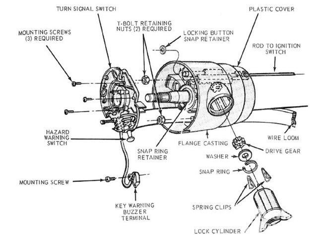
A comprehensive Ford ignition lock cylinder diagram illustrates more than just a keyhole; it represents a sophisticated interface between mechanical security and electrical distribution. At its core, the assembly consists of the lock cylinder itself, which houses a series of spring-loaded pins or wafers. When the correct key is inserted, these pins align at the shear line, allowing the cylinder to rotate within the ignition lock housing. This housing is typically bolted to the steering column using shear bolts for theft prevention.
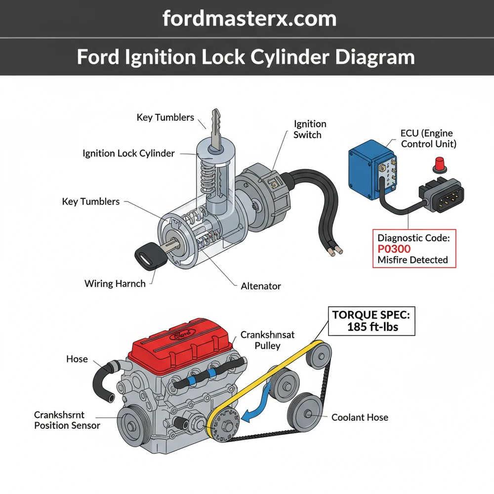
Beyond the mechanical lock, the diagram shows the ignition switch—an electrical component mounted at the rear of the housing. As you turn the key, a physical actuator rod or a direct gear interface moves the internal contacts of the switch. These contacts distribute power to various circuits, including the accessory, run, and start positions. In modern Ford vehicles, the diagram also includes the Passive Anti-Theft System (PATS) transceiver ring. This plastic halo sits around the face of the lock cylinder and communicates wirelessly with a chip inside your key. If this transceiver fails to read the key, the ECU (Engine Control Unit) will disable the fuel system, often triggered by a blinking security light on the dashboard.
The ignition lock cylinder is purely mechanical. It serves as the physical “gatekeeper” for the ignition switch, which is the electrical component responsible for sending power to the starter motor and engine management systems.
– Visual Representation of a Ford Ignition Lock Cylinder including the lock housing, tumbler assembly, PATS transceiver, and electrical switch interface.
In many Ford models, the diagram will also highlight the steering lock pin. This is a spring-loaded bolt that extends into the steering column shaft when the key is removed, preventing the wheel from turning. If the steering wheel is turned hard against this pin while the vehicle is parked, it can create “steering lock bind,” making it feel as though the ignition lock cylinder has failed when it simply requires a nudge of the steering wheel to release pressure.
How to Use the Diagram for Installation and Repair

Interpreting a Ford ignition lock cylinder diagram requires a systematic approach. Before beginning any work, you must gather the necessary tools: a screwdriver set (often Torx T-20 or T-27 for Ford columns), a small punch or hex key for the release pin, and safety glasses.
Always disconnect the negative battery terminal before working on the steering column. This prevents accidental airbag deployment and protects the ECU from electrical surges while you are disconnecting the ignition switch or PATS transceiver.
Follow these steps to utilize the diagram for a successful replacement:
- ✓ Access the Column: Remove the plastic shrouds surrounding the steering column. These are usually held by three or four screws on the underside. Refer to your diagram to locate the hidden tabs that snap the two halves together.
- ✓ Identify the Release Hole: Look at your diagram to find the small access hole on the ignition lock housing. This is typically located on the bottom or side of the metal casting.
- ✓ Set the Ignition Position: Insert your key and turn it to the “RUN” or “ON” position. The release pin inside the housing cannot be depressed unless the cylinder is in this specific orientation.
- ✓ Depress the Release Pin: Use a small punch or an Allen wrench to push the pin through the access hole. While holding the pin down, gently pull the lock cylinder out of the housing.
- ✓ Inspect the Housing: Use a flashlight to look inside the housing. Check for debris or broken pieces of the ignition switch actuator rod, which is a common failure point in older Ford trucks and SUVs.
- ✓ Install the New Cylinder: Ensure the new cylinder is set to the “RUN” position to match the internal slot of the ignition switch. Slide it into the housing until the release pin clicks into place.
- ✓ Test and Reassemble: Reconnect the battery and test the key in all positions. If your vehicle has a PATS system, you may need to perform a key programming sequence as outlined in your owner’s manual before the engine will stay running.
When reassembling the column, ensure all wiring harnesses for the multi-function switch and the PATS transceiver are tucked away correctly to avoid pinching. Note that the mounting screws for the column shrouds do not require a high torque spec; hand-tight is sufficient to avoid cracking the plastic.
Troubleshooting Common Ignition Failures
The Ford ignition lock cylinder diagram is an invaluable tool for troubleshooting. One of the most common issues is a key that goes into the slot but refuses to turn. This usually indicates that the internal wafers are worn down or stuck. If you cannot turn the key to the “RUN” position, you cannot access the release pin to remove the cylinder, often necessitating a more destructive removal process by a locksmith.
Another frequent problem involves the vehicle’s electronics. If you turn the key and the dashboard lights come on but the engine doesn’t crank, the diagram helps you identify the ignition switch at the back of the assembly as the likely culprit. If the engine cranks but dies immediately, look toward the PATS transceiver. A failing ignition system can sometimes trigger a check engine light or prevent an OBD-II scanner from communicating with the ECU. This happens because the “RUN” circuit of the ignition switch provides the necessary wake-up signal to the diagnostic port.
If your key is sticky, avoid using WD-40. Instead, use a specialized dry graphite lubricant. Liquid oils attract dust and lint, which eventually turn into a paste that jams the delicate tumblers inside the lock cylinder.
If you encounter a diagnostic code related to the immobilizer or ignition circuit, use the diagram to trace the wiring from the column to the main harness. Occasionally, what looks like a mechanical failure is actually a loose ground or a chafed wire near the steering tilt mechanism.
Maintenance and Long-Term Reliability
To avoid having to use a Ford ignition lock cylinder diagram for an emergency repair, regular maintenance is key. Heavy keychains are the leading cause of premature ignition failure. The constant weight bouncing while you drive puts leverage on the lock cylinder, eventually bending the internal pins and wallowing out the housing. It is best to keep your ignition key on a separate quick-release ring.
Furthermore, do not ignore the early warning signs of failure. If you have to “jiggle” the key to get it to turn, or if it occasionally gets stuck in the accessory position, the cylinder is signaling its imminent demise. Replacing it while it still turns is a 15-minute job; replacing it once it is seized is a multi-hour ordeal.
While you are working on the ignition system, it is a good time to perform a general inspection of related components. Check that your accessory belt is in good condition, as the ignition switch powers the charging system that relies on it. While the ignition doesn’t directly affect the timing chain or coolant flow, a healthy starting system ensures that these critical engine components are not subjected to the strain of repeated, failed starting attempts.
In conclusion, understanding the Ford ignition lock cylinder diagram empowers you to take control of your vehicle’s maintenance. Whether you are dealing with a faulty PATS transceiver or a jammed tumbler, the diagram serves as your roadmap to a successful repair. By following the proper safety protocols and using quality replacement parts, you ensure that your Ford remains ready to hit the road whenever you turn the key.
Step-by-Step Guide to Understanding the Ford Ignition Lock Cylinder Diagram: Identification Guide
Identify the correct ignition lock cylinder components using the diagram to differentiate between the housing, the tumblers, and the transceiver ring.
Locate the small access hole on the bottom of the steering column shroud while the key is turned to the ‘Run’ position to find the release pin.
Understand how the internal pins must align with the key cuts to allow the cylinder to rotate and release from the steering column housing.
Connect the new cylinder by sliding it into the column until the retention pin clicks, ensuring it properly engages with the ignition switch actuator.
Verify that the steering wheel locks and unlocks correctly and that the ECU recognizes the transponder signal to avoid a check engine light or security lockout.
Complete the installation by reattaching the plastic steering column shrouds, ensuring each screw meets the recommended torque spec to prevent rattling or vibration during driving.
Frequently Asked Questions
Where is the Ford ignition lock cylinder located?
The Ford ignition lock cylinder is located on the right side of the steering column, housed within a metal sleeve. It is typically accessed by removing the plastic shrouds. Identifying the small access hole for the release pin on the underside of the column is crucial for removing the old cylinder assembly.
What does a Ford ignition lock cylinder diagram show?
A Ford ignition lock cylinder diagram provides an exploded view of the tumblers, springs, and the lock housing. It identifies the mechanical interface between the key and the ignition switch. The diagram also highlights the transceiver ring that communicates with the ECU to allow the engine to crank and run.
How many connections does the ignition cylinder have?
The ignition lock cylinder itself is primarily a mechanical component, but it interacts with three main electrical pathways. These include the key-in-warning switch, the passive anti-theft system (PATS) transceiver, and the ignition switch. The diagram shows how the mechanical rotation triggers these circuits to start the vehicle and power accessories.
What are the symptoms of a bad Ford ignition lock cylinder?
Common symptoms include a key that is difficult to turn, a key that gets stuck in the ‘on’ or ‘start’ position, or the vehicle failing to recognize the key. If the cylinder fails to engage the switch properly, it may trigger a check engine light or a specific B-series diagnostic code.
Can I replace the Ford ignition lock cylinder myself?
Replacing a Ford ignition lock cylinder is a common DIY task if you have the working key. Without the key, the process involves drilling the retention pin. However, if your vehicle uses a transponder key, you may need an OBD-II tool to program the new keys into the vehicle computer.
What tools do I need for this ignition cylinder task?
To replace the cylinder, you need a basic screwdriver set to remove the column shrouds and a small punch or awl to depress the release pin. If the failure caused electronic issues, an OBD-II scanner is helpful for clearing a diagnostic code or resetting the anti-theft system during installation.


