Ford HEI Distributor Wiring Diagram: Easy Setup Guide
A Ford HEI distributor wiring diagram illustrates a streamlined ignition setup. You connect a 12V hot wire to the BATT terminal on the cap. Ensure the unit has a clean ground wire path through the engine block. This DC system eliminates the need for a traveler wire or neutral wire, using the common terminal for power.
📌 Key Takeaways
- HEI distributors simplify wiring by integrating the coil into the cap.
- A full 12V power source is required for the HEI system to function correctly.
- Proper grounding through the distributor base is essential for a clean spark.
- The TACH terminal is used for connecting an aftermarket tachometer.
- Replacing old points systems with HEI improves fuel economy and starting.
Upgrading a classic Ford engine with a High Energy Ignition (HEI) system is one of the most effective ways to improve cold-start reliability, throttle response, and overall fuel efficiency. To perform this upgrade correctly, understanding a specific ford hei distributor wiring diagram is essential, as the wiring requirements differ significantly from the original points-based or Duraspark systems. This article provides a comprehensive breakdown of the wiring sequence, terminal identifications, and voltage requirements needed for a successful installation. You will learn how to identify the correct power sources, choose the right wire gauges, and ensure your ignition system receives the full battery voltage it requires to function optimally.
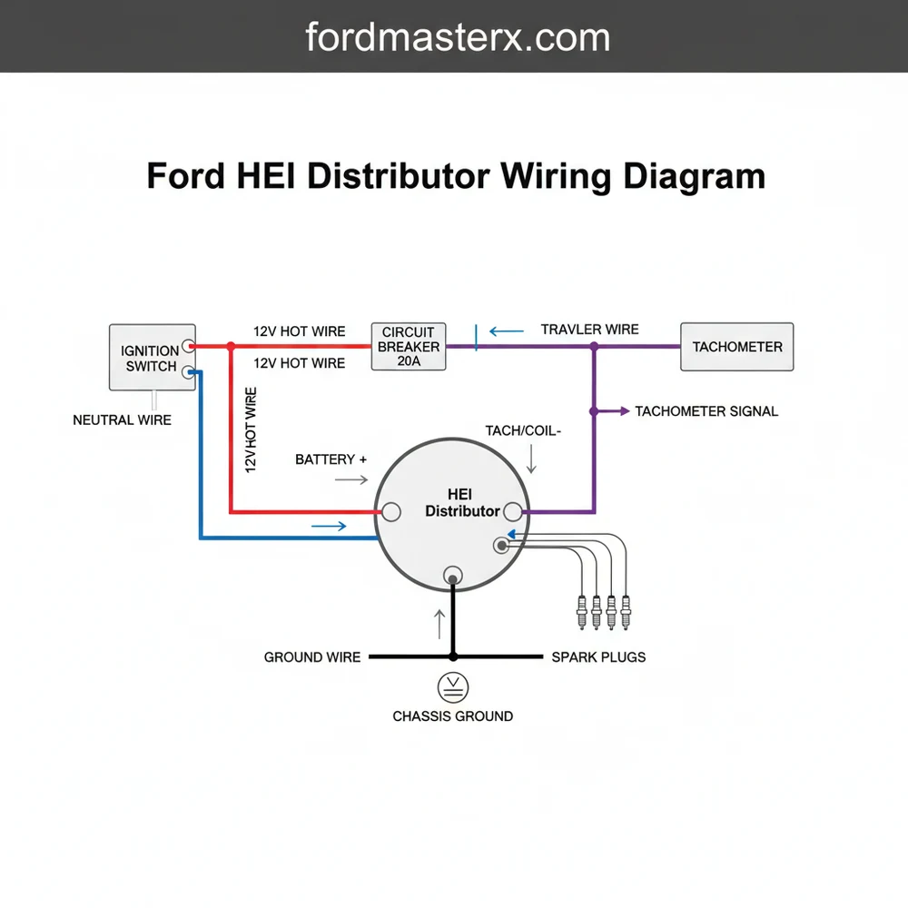
The ford hei distributor wiring diagram illustrates a streamlined ignition system where the coil is integrated directly into the distributor cap. This “coil-in-cap” design eliminates the need for an external spark coil and the messy “traveler wire” configurations found in older setups. The diagram primarily focuses on two main connection points located on the side of the distributor cap: the BAT (Battery) terminal and the TACH (Tachometer) terminal. These terminals are often housed within a keyed plastic connector to prevent improper orientation.
In the diagram, the BAT terminal acts as the common terminal for the entire ignition system’s power supply. Unlike vintage Ford systems that used a resistance wire—often referred to in electrical terms as a neutral wire or ballast wire—to drop the voltage to 7 or 9 volts, the HEI system requires a full 12-volt “hot wire” connection at all times when the key is in the “On” and “Start” positions. The diagram will show a thick-gauge wire (typically 10 or 12 AWG) running from a switched 12V source directly to this BAT terminal. The internal components, including the four-pin or seven-pin ignition module and the pickup coil, are grounded through the distributor housing itself, making the physical installation into the engine block a critical part of the grounding circuit.
The TACH terminal in the diagram is an optional connection point. If your Ford vehicle is equipped with an aftermarket or factory tachometer, the signal wire from that gauge connects here. The diagram also visualizes the internal brass screw or spade connections that link the external terminals to the internal coil and module. Understanding these visual cues ensures that you do not accidentally cross-polarize the distributor, which could result in a blown module or a damaged internal coil.
Visual representation of a Ford V8 HEI distributor showing the BAT and TACH terminals, the 12V switched power source, and the bypass of the factory ballast resistor.
To properly implement the ford hei distributor wiring diagram, follow these detailed steps to ensure a safe and professional installation.
- 1. Disconnect the Battery: Always begin by disconnecting the negative battery cable. Since you will be working with a high-amperage “hot wire,” preventing accidental shorts is a primary safety requirement.
- 2. Locate a 12V Switched Power Source: You must find a wire that provides 12 volts only when the ignition key is in the “Run” and “Start” positions. In many older Fords, the wire attached to the positive side of the old coil is a resistance wire. You cannot use this as-is because it provides insufficient voltage. Instead, trace this wire back to the ignition switch or use a relay triggered by the original wire to provide a fresh 12V feed.
- 3. Select the Correct Wire Gauge: HEI systems draw significantly more current than points systems. Use a 10-gauge or 12-gauge “hot wire” for the main power feed. Using a smaller gauge wire can lead to voltage drops, which will weaken the spark at high RPMs and potentially cause the module to overheat.
- 4. Identify the BAT Terminal: Look at the side of the distributor cap. The terminals are usually labeled. The BAT terminal is the one that requires the 12V feed. Use a high-quality female spade connector or the specific HEI pigtail connector to ensure a tight, vibration-resistant fit.
- 5. Connect the Tachometer (Optional): If you have a tachometer, connect its signal wire to the TACH terminal. Ensure this wire is routed away from the spark plug wires to prevent electromagnetic interference (EMI) from causing “bouncing” needle readings on your gauge.
- 6. Verify Grounding: Ensure the base of the distributor and the engine block surface are clean and free of excessive paint or rust. The distributor relies on the hold-down clamp and the engine block to complete the ground circuit. A poor ground is a leading cause of HEI module failure.
- 7. Set the Firing Order: Refer to your specific Ford engine manual (e.g., 302 vs. 351W) to ensure the spark plug wires are installed in the correct sequence. The HEI cap is larger than the stock cap, so ensure you have enough clearance from the air cleaner and firewall.
- 8. Reconnect and Test: Reconnect the battery and use a voltmeter to verify that the BAT terminal is receiving at least 12.5 volts while the engine is cranking and running.
Vintage Ford vehicles often use a pink or red-with-green-stripe wire that contains a built-in resistor. If you connect this wire directly to your HEI distributor, the system will only receive about 9 volts, leading to poor performance, hard starts, and eventual engine stalling. Always bypass this resistance wire to provide a full 12V “hot wire” signal.
Even with a clear ford hei distributor wiring diagram, users often encounter specific troubleshooting hurdles. The most common issue is the “no-start” condition after installation. This is frequently traced back to the ignition switch. On some Fords, the power source chosen might provide 12V in the “Run” position but cut power during the “Start” (cranking) position. If the engine only fires when you release the key, you have tapped into the wrong circuit.
Another frequent problem is EMI interference. Because HEI systems produce such high voltage, they can interfere with radio equipment or electronic fuel injection (EFI) sensors. If you notice your engine stumbling or your radio buzzing, check that your “traveler wire” (the main power feed) and spark plug wires are high-quality, shielded components. Furthermore, if the engine misfires at high speeds, use a multimeter to check the voltage at the common terminal. If the voltage drops below 12V as RPMs increase, your wire gauge is likely too small, or your alternator cannot keep up with the ignition demand.
HEI systems generate upwards of 50,000 volts. Never touch the distributor or spark plug wires while the engine is running. Additionally, ensure the brass screw terminals inside the cap are tight; a loose connection here can lead to internal arcing, which will melt the distributor cap and potentially cause an engine bay fire.
To get the most out of your Ford HEI conversion, consider these professional tips. First, because the HEI produces a much hotter spark than a standard points system, you should increase your spark plug gap. Most Ford V8s running HEI benefit from a gap between .045 and .055 inches. This wider gap allows for a larger spark kernel, which more efficiently ignites the air-fuel mixture.
Maintenance is also simplified with HEI, but not eliminated. Periodically inspect the brass screw terminals and the carbon button inside the cap. If the carbon button shows signs of burning or cracking, replace it immediately to prevent damage to the internal coil. Using a small amount of dielectric grease on the spark plug wire boots and the BAT/TACH terminals will prevent moisture intrusion and corrosion, which is vital for maintaining consistent voltage.
When purchasing your distributor, look for units that feature a CNC-machined 6061-T6 aluminum housing and a high-output 50,000-volt coil. Cheap “no-name” distributors often use inferior ignition modules that fail under high-heat conditions. Investing in a quality brand can save you from being stranded on the side of the road.
Lastly, consider your timing curve. Most HEI distributors come with an adjustable vacuum advance. Using the ford hei distributor wiring diagram to get the engine running is only the first half of the job; fine-tuning the mechanical and vacuum advance will ensure your Ford engine reaches its full power potential. By following the wiring sequence accurately and ensuring a robust 12V power supply, you can enjoy the modern benefits of high-energy ignition in your classic Ford vehicle for years to come.
Step-by-Step Guide to Understanding the Ford Hei Distributor Wiring Diagram: Easy Setup Guide
Identify the terminals – Find the BATT and TACH ports located on the side of the distributor cap.
Locate the power source – Find a 12V hot wire that provides power only when the ignition is in the ‘on’ or ‘crank’ position.
Understand the ground – Ensure the engine block surface is clean to provide a solid ground wire path through the distributor base.
Connect the hot wire – Route the power wire to the common terminal labeled BATT, ensuring it is fused appropriately.
Verify the absence of resistance – Ensure no ballast resistor, traveler wire, or neutral wire from an old system is restricting voltage.
Complete the setup – Secure the cap, check your firing order, and use a timing light to set the final ignition advance.
Frequently Asked Questions
Where is the Ford HEI distributor located?
The distributor is located at either the front or the rear of the engine block, depending on the engine family. For Small Block Fords (SBF), it is at the front; for FE and 385-series Big Blocks, it is also at the front, while older Y-blocks place it at the rear.
What does this wiring diagram show?
This diagram shows the routing of the primary 12V power source to the distributor cap. It identifies the battery (BATT) terminal, the tachometer (TACH) terminal, and the internal coil connection. It highlights how the single-wire setup replaces complex external coil and ballast resistor configurations used in older systems.
How many wires does an HEI distributor have?
Most Ford HEI distributors require only one main connection, which is the 12V hot wire for ignition. An optional second wire can be connected to the TACH terminal for a tachometer. Internally, the ground wire connection is established through the distributor housing when it is bolted to the engine.
What are the symptoms of a bad HEI distributor?
Symptoms include engine misfiring, difficulty starting, or a complete no-start condition. You may also experience engine stalling when warm or visible carbon tracking inside the distributor cap. A failed module or internal coil is often the culprit when spark is weak or non-existent at the spark plugs.
Can I install an HEI distributor myself?
Yes, installing an HEI distributor is a popular DIY project because it eliminates the messy wiring of external coils. You only need to provide a switched 12V source. However, you must be comfortable with setting engine timing to ‘Top Dead Center’ to ensure the gears and rotor align correctly during installation.
What tools do I need for this task?
You will need a basic socket set, a timing light to verify spark advance, a wire crimping tool for the power lead, and potentially a multimeter. The multimeter helps ensure your hot wire provides a constant 12V rather than the reduced voltage found in older resistor-wire Ford ignition circuits.


