Ford Fuel Tank Selector Switch Wiring Diagram: Easy Guide
The Ford fuel tank selector switch wiring diagram illustrates how electrical current flows from the dash switch to the tank selector valve. It shows the hot wire from the fuse, the traveler wire pathways to different tanks, and the common terminal that routes the signal to the fuel gauge for accurate readings.
📌 Key Takeaways
- Provides a roadmap for dual-tank electrical systems.
- Identify the common terminal to understand signal routing.
- Ensure the ground wire is secure to prevent gauge erraticism.
- Use a multimeter to test voltage at the selector valve.
- Refer to this when switching between tanks fails or gauges malfunction.
Obtaining a correct ford fuel tank selector switch wiring diagram is the most critical step when diagnosing fuel delivery issues in classic dual-tank vehicles. For many Ford truck owners, the ability to switch between a primary and secondary reservoir is a defining feature of their vehicle’s utility, but the complexity of the wiring can lead to significant frustration when components fail. This article provides a comprehensive breakdown of the electrical connections, wire colors, and pin configurations found in the selector system. By understanding the flow of current from the dash switch to the pumps and sending units, you will learn how to accurately troubleshoot and repair your fuel system to ensure reliable performance across both tanks.
Understanding the internal logic of the selector switch is essential for a successful repair. Most Ford systems utilize a Double Pole Double Throw (DPDT) switch, which essentially acts as a traffic controller for two separate circuits: the power supply to the fuel pumps and the signal return for the fuel level gauge. When you toggle the switch on your dashboard, you are physically moving a bridge that connects the source of voltage to the intended destination while simultaneously shifting the gauge’s “common terminal” to read from the corresponding tank’s sending unit.
The typical Ford 6-pin connector layout is organized into two distinct rows or a circular pattern depending on the specific model. The “hot wire,” usually arriving from the fuel pump relay or inertia switch, enters the switch at a central terminal. From there, the current is directed through a “traveler wire” to either the front fuel pump or the rear fuel pump. On the gauge side of the switch, the circuit manages the resistance signal sent from the fuel tanks. The “neutral wire” or return path ensures that the circuit is completed back to the vehicle’s chassis ground. In many aftermarket or heavy-duty Ford switches, you may find a “brass screw” terminal designed for a dedicated ground wire to prevent the “floating ground” issues common in older plastic-housed units.
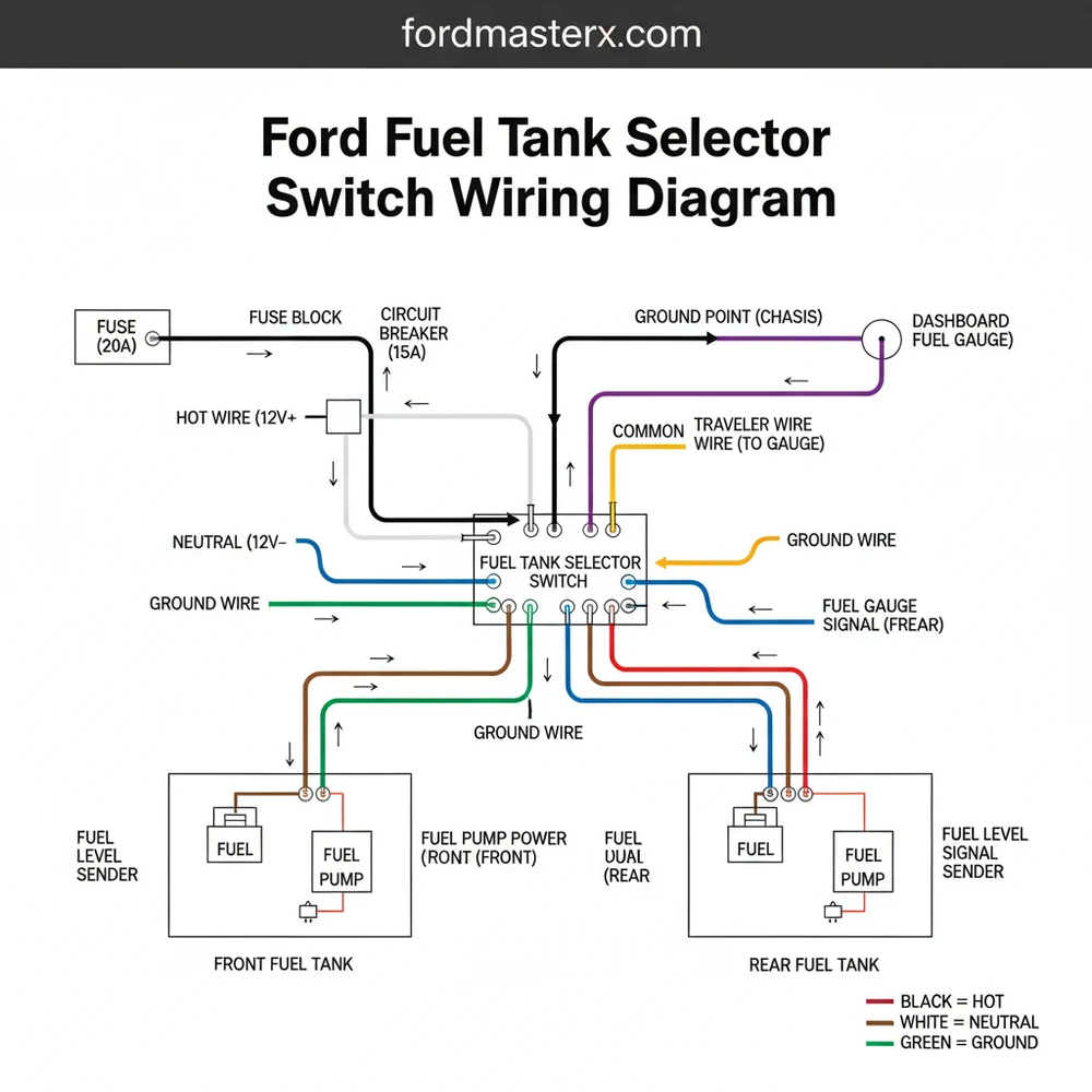
This diagram illustrates the 12V power input, the dual pump output traveler wires, and the gauge sending unit input/output sequence. Note the specific color-coded paths for the front (primary) and rear (auxiliary) circuits.
Most Ford trucks from the mid-1970s through the late 1990s follow a relatively consistent color-coding scheme, though variations exist. Generally, a Red/Grey or Brown/White wire serves as the main 12V power supply. The traveler wires for the pumps are often colored Red/White for the front tank and Brown/White for the rear. The gauge wires, which are thinner in “gauge” than the power wires, typically feature a Yellow/White or Blue/Yellow stripe.
In EFI (Electronic Fuel Injection) models, the selector switch doesn’t just move electricity; it often triggers a motorized selector valve located on the frame rail. In these systems, the switch reverses polarity to move the valve motor back and forth, making the ford fuel tank selector switch wiring diagram slightly more complex than in carbureted models.
To interpret and implement the wiring diagram correctly, follow these systematic steps for installation or diagnosis. Before starting, ensure you have a digital multimeter capable of measuring DC voltage and resistance, wire stripping tools, and heat-shrink connectors if you are performing a replacement.
Step 1: Identify and Label the Existing Wires
Before removing your old switch, use masking tape to label each wire according to its function. Refer to the ford fuel tank selector switch wiring diagram to confirm which wire is the “hot wire” (power in) and which are the “traveler wires” (power out to pumps). Identifying the “common terminal” for the gauge signal is equally important to avoid a non-functioning fuel needle later.
Step 2: Disconnect the Battery
Safety is paramount when working with the fuel system. Even though you are working inside the cab, the wires you are handling carry significant amperage and are located near fuel lines under the truck. Disconnect the negative battery terminal to prevent accidental shorts that could damage the sensitive fuel sending units or blow a fuse.
Step 3: Test for Source Voltage
Using your multimeter, set it to the 20V DC range. Turn the ignition key to the “On” or “Run” position (you may need a helper to cycle the key if the fuel pump relay only primes for a few seconds). Probe the main power input wire. You should see a reading of approximately 12.6V, which is the standard battery voltage. If no voltage is present, the issue lies further up the circuit in the fuse box or the inertia switch.
Step 4: Map the Gauge Continuity
Switch your multimeter to the Ohms (resistance) setting. Connect one lead to the “common terminal” on the switch connector that leads to the dashboard gauge. Connect the other lead to the wires coming from the fuel tanks. When the tank is full, you should see low resistance (roughly 10-15 ohms on older Fords); when empty, the resistance will be much higher (around 73-80 ohms). This confirms the “neutral wire” and sending unit circuits are intact.
Step 5: Connect the New Switch
Following the diagram, attach the wires to the corresponding pins. If your replacement switch uses a “brass screw” for the ground, ensure it is tightened securely against a clean metal surface or connected to a dedicated ground wire. Proper grounding is essential for accurate gauge readings.
Step 6: Verify Pump Operation
Reconnect the battery and toggle the switch between the “Front” and “Rear” positions. You should hear the distinct hum of the fuel pump engaging in each tank. If one tank works but the other doesn’t, check the specific traveler wire connection for that circuit.
Step 7: Final Gauge Check
Observe the fuel gauge on the dashboard. It should move to reflect the level of whichever tank is selected. If the needle jumps to past full or stays at empty, there is likely a cross-connection between the power “hot wire” and the gauge signal wire.
Never bypass the fuel pump inertia switch. If you are using the wiring diagram to hardwire a pump for testing, do so only temporarily. The inertia switch is a safety device that cuts power to the fuel pumps in the event of a collision.
Even with a perfect ford fuel tank selector switch wiring diagram, you may encounter troubleshooting hurdles. One of the most common issues is a “lazy” switch, where the internal contacts have become pitted or corroded. This often manifests as the truck running fine on one tank but sputtering or dying shortly after switching to the second, despite the second tank being full.
Another frequent problem involves the fuel gauge. If the gauge reads accurately for one tank but pegs to the maximum limit on the other, the “traveler wire” for that specific sending unit is likely grounded or disconnected. If the gauge does not move at all regardless of switch position, the “common terminal” connecting the switch to the dash cluster is the primary suspect. Using the diagram to trace the wire from the switch back to the cluster can help identify broken insulation or a loose pin in the firewall bulkhead connector.
- ✓ Intermittent Power: Often caused by a loose connection at the “hot wire” terminal.
- ✓ Erratic Gauge Readings: Usually results from a poor “ground wire” connection or high resistance in the switch.
- ✓ Pump Running Constantly: Can indicate a short circuit where the traveler wire is touching a constant power source.
When replacing components, always opt for high-quality switches that meet or exceed OEM specifications. Cheap aftermarket switches often use thinner internal copper plates which can overheat when subjected to the continuous amperage required by high-pressure EFI fuel pumps. Ensure the wire “gauge” you use for any repairs matches the factory harness; usually, 14-gauge wire is used for power delivery to prevent voltage drop over the length of the vehicle.
Apply a small amount of dielectric grease to the switch terminals before plugging in the harness. This prevents moisture intrusion and corrosion, which are the leading causes of switch failure in trucks used in humid or salt-heavy environments.
Regular maintenance of the fuel selector system involves more than just the electrical side. Periodically check the fuel selector valve on the frame rail for leaks. If the valve sticks mechanically, the electrical switch may still send power to the pump, but the fuel won’t reach the engine. In such cases, the wiring diagram is useful for confirming that the electrical signal is reaching the valve’s motor, allowing you to isolate the failure to the mechanical component rather than the wiring.
By following this ford fuel tank selector switch wiring diagram and the associated troubleshooting steps, you can maintain the integrity of your Ford’s dual-tank system. Proper terminal identification, understanding the role of the traveler wires, and ensuring a solid ground will keep your fuel delivery system operating smoothly for years to come. Whether you are performing a simple switch replacement or a full harness restoration, accurate wiring is the foundation of a reliable vehicle.
Step-by-Step Guide to Understanding the Ford Fuel Tank Selector Switch Wiring Diagram: Easy Guide
Identify the hot wire entering the switch from the fuse block to ensure the system is receiving power.
Locate the common terminal on the back of the switch which connects the fuel gauge to the sending units.
Understand how the traveler wire directs the electrical load to either the front or rear fuel pump assembly.
Connect the ground wire to a clean metal surface to ensure the circuit completes without resistance.
Verify that the neutral wire and signal wires are properly seated in the harness to prevent gauge issues.
Complete the installation by testing both tanks to confirm the switch successfully alternates fuel delivery and gauge accuracy.
Frequently Asked Questions
Where is the fuel tank selector switch located?
The fuel tank selector switch is typically located on the dashboard to the left or right of the steering column. In older Ford trucks, it may be integrated into the heater controls or a standalone toggle. The corresponding selector valve is usually mounted on the inner frame rail under the driver’s side.
What does this wiring diagram show?
The Ford fuel tank selector switch wiring diagram displays the electrical paths connecting the toggle switch to the dual tanks. It highlights how the hot wire provides power while the traveler wire system redirects that power to either the front or rear tank fuel pumps and sending units for operation.
How many wires does the selector switch have?
Most Ford selector switches feature six pins. These include a hot wire for power, a neutral wire for signal return, ground connections, and traveler wires that toggle between the front and rear sending units. The central common terminal acts as the pivot point for directing the fuel gauge reading.
What are the symptoms of a bad selector switch?
Symptoms of a faulty selector switch include the truck stalling when switching tanks, the fuel gauge showing ’empty’ regardless of fuel level, or the inability to draw fuel from one specific tank. If the traveler wire is damaged, power won’t reach the selected fuel pump, resulting in a no-start condition.
Can I replace the selector switch myself?
Yes, replacing the selector switch is a straightforward DIY task. Since the wiring is modular, you can usually unplug the old harness and snap in a new unit. However, tracing faults in the wiring diagram requires a basic understanding of electrical circuits and the use of a multimeter for testing.
What tools do I need for this task?
To troubleshoot or install a selector switch, you will need a digital multimeter for testing voltage and continuity. A set of screwdrivers or trim removal tools is necessary to access the dash area. Additionally, wire strippers and crimpers are helpful if you need to repair a damaged traveler wire.


