Ford Fiesta Air Conditioning System Diagram: Complete Layout
The Ford Fiesta air conditioning system diagram illustrates the complete refrigerant flow through the compressor, condenser, and evaporator. This system layout allows owners to identify specific component locations and hose routing, making it essential for diagnosing leaks or poor cooling performance in your vehicle’s AC configuration and electrical wiring structure.
📌 Key Takeaways
- Visualizes the cycle of refrigerant between high and low-pressure sides
- Identifies the compressor as the primary mechanical component for cooling
- Always wear safety goggles when working around pressurized AC lines
- Use the diagram to locate specific pressure switches and sensors
- Necessary for tracing refrigerant leaks or electrical signal failures
The Ford Fiesta has long been a staple of the subcompact car market, known for its agile handling and efficient design. However, maintaining the comfort of the cabin relies heavily on the performance of the Air Conditioning (AC) system. For a DIY enthusiast, the AC system can often seem like a labyrinth of pressurized hoses, sensitive sensors, and complex wiring. Understanding the Ford Fiesta air conditioning system diagram is the first step toward diagnosing a failure or performing a successful repair. This guide provides a deep dive into the mechanical and electrical layout of the Fiesta’s HVAC system, focusing on the most common models (Mk6 and Mk7), to help you navigate the system with confidence.
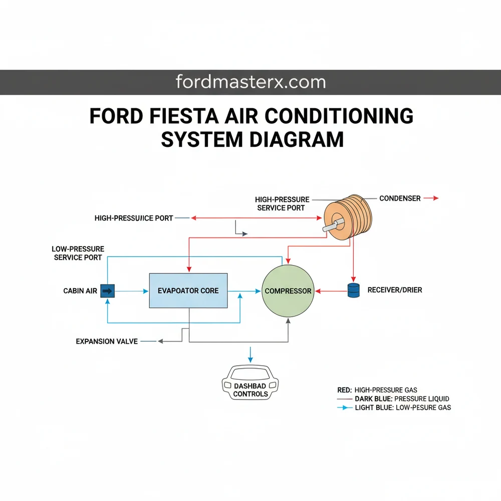
Main Components and System Features
The Ford Fiesta AC system operates on a standard vapor-compression refrigeration cycle, but its compact engine bay means components are tightly packed. To effectively use a diagram, you must first be able to identify these physical parts and understand their role in the circuit.
- The Compressor: Located at the lower-front section of the engine, driven by the serpentine belt. It is the heart of the system, responsible for compressing low-pressure refrigerant gas into a high-pressure gas. In most Fiestas, the compressor utilizes an electromagnetic clutch (controlled by a 12V signal) to engage and disengage.
- The Condenser: Positioned directly in front of the engine radiator. It looks like a thin radiator and functions to dissipate heat from the high-pressure refrigerant, turning it from a gas into a high-pressure liquid.
- The Receiver/Drier (or Accumulator): Usually a small cylindrical canister located near the condenser or firewall. It contains a desiccant to remove moisture from the refrigerant and acts as a temporary storage vessel.
- The Expansion Valve (TXV): Located at the firewall where the AC lines enter the cabin. This component regulates the flow of refrigerant into the evaporator, causing a pressure drop that creates the cooling effect.
- The Evaporator: Tucked deep inside the dashboard within the HVAC heater box. This is where the actual cooling of the cabin air occurs.
- Pressure Switches: Ford Fiestas typically use a High-Pressure Switch and a Low-Pressure Switch (or a combined Transducer). These are safety devices that tell the Engine Control Module (ECM) to cut power to the compressor if pressures are too high (preventing explosion) or too low (preventing pump damage due to a leak).
How to Use and Read the AC Diagram

A Ford Fiesta AC diagram is usually split into two parts: the Refrigerant Flow Diagram (mechanical) and the Electrical Schematic (logic). For DIYers, the electrical schematic is often the most vital tool for troubleshooting “no-cool” conditions.
1. Identifying Wire Colors
Ford uses a specific coding system for their wiring harnesses. When looking at a Fiesta wiring diagram, wires are labeled with a base color and often a stripe color. Common codes include:
- BK: Black (Usually Ground)
- BU: Blue
- GN: Green
- GY: Grey
- VT: Violet
- YE: Yellow
- WH: White
For example, a wire labeled VT-GN is a Violet wire with a Green stripe. On many Mk7 Fiestas, the wire leading to the AC compressor clutch coil is often VT-GY or GN-WH. Knowing this allows you to test for 12V power at the compressor connector using a multimeter.
2. Understanding the Signal Path
When you press the AC button on the dash, the signal doesn’t go directly to the compressor. In a modern Fiesta, the path is as follows:
- The HVAC module sends a request via the CAN-bus network to the BCM (Body Control Module).
- The BCM checks the AC Pressure Sensor (usually located on the high-side line near the engine mount).
- If the pressure is within the safe range (typically between 30 psi and 350 psi), the BCM sends a signal to the AC Relay in the engine compartment fuse box.
- The relay closes, sending 12V from a high-amp fuse to the compressor clutch.
3. Fuse and Relay Locations
In most Ford Fiestas (2008–2017), the critical electrical components are located in the Engine Compartment Fuse Box (next to the battery).
- AC Clutch Relay: Often labeled as R11 or K32 depending on the specific year.
- AC Fuse: Typically a 10A or 15A fuse, often found at position F2 or F22.
Practical Measurements and Specifications

To use the diagram effectively for repairs, you need to know the specific capacities for your Fiesta. Using the wrong amount of refrigerant or oil is a leading cause of system failure after a DIY repair.
Refrigerant Capacity
Most 2008–2017 Ford Fiestas require R134a refrigerant. Models manufactured after 2017 may use R1234yf. Check the sticker under the hood for confirmation.
- Mk7 Fiesta (1.6L/1.0L): Approximately 460 grams to 500 grams (1.01 lbs – 1.1 lbs).
- PAG Oil Type: PAG 46 is standard for most Fiesta compressors.
- Oil Capacity: Total system capacity is usually around 120ml to 150ml. If only replacing the compressor, you typically only add back what was drained from the old unit.
Electrical Readings
When using your diagram to probe the system, look for these values:
- Clutch Coil Resistance: With the engine off and the connector unplugged, the compressor clutch coil should show roughly 3.0 to 4.5 Ohms. If it shows “OL” (Open Loop), the coil is burnt out.
- Pressure Sensor Voltage: The pressure transducer usually has three wires: 5V Reference, Ground, and Signal. At a resting pressure (engine off), the signal wire should typically read between 0.5V and 1.5V.
Troubleshooting Common Fiesta AC Issues
Using the diagram and component locations, you can systematically diagnose the most frequent failures in the Ford Fiesta.
1. The “Blower Motor Only Works on 4” Problem
This is a classic Fiesta issue. If your fan only works on the highest setting, the Blower Motor Resistor has failed. In the diagram, the resistor sits between the fan switch and the motor. In a RHD Fiesta, it’s located in the driver’s footwell; in a LHD Fiesta, it’s in the passenger footwell near the center console. The resistor pack uses thermal fuses that blow when the motor draws too much current or the cabin filter is clogged.
2. Compressor Clutch Won’t Engage
If the diagram shows power going to the relay but the clutch isn’t clicking, check the air gap. Over time, the clutch plate wears down, and the magnetic field can no longer pull it in. The gap should be between 0.3mm and 0.5mm. You can often fix this by removing one of the small shims (washers) from behind the clutch plate to bring it closer to the pulley.
3. Intermittent Cooling (The Freeze-Up)
If the AC works for 20 minutes and then stops, but works again after the car sits, the evaporator may be freezing. This is often caused by a faulty Evaporator Temperature Sensor (found inside the HVAC box). The diagram will show this sensor’s resistance values, which the BCM uses to cycle the compressor off before ice forms.
4. Leaks at the Condenser
Because the Fiesta sits low to the ground, the condenser is highly susceptible to rock punctures. Use a UV light and yellow glasses to inspect the condenser fins for bright green dye (most Fiestas come with dye from the factory). If you see a oily, glowing spot, the condenser must be replaced.
Maintenance Tips for Longevity
To avoid having to rely on your troubleshooting diagram too often, follow these maintenance steps:
- Replace the Cabin Air Filter: A clogged filter restricts airflow over the evaporator, which can cause the compressor to work harder and eventually fail. In the Fiesta, this is located behind the center console side trim.
- Run the AC in Winter: Run the AC for at least 10 minutes once a week during winter. This circulates the PAG oil and keeps the internal seals lubricated, preventing refrigerant leaks.
- Clear the Condenser: Periodically spray low-pressure water through the front grille to wash away salt, dirt, and bugs from the condenser fins.
By combining a high-quality Ford Fiesta air conditioning system diagram with the practical locations and electrical data provided here, you can move from guesswork to precision repair. Whether you are replacing a blown resistor or testing a compressor relay, understanding the flow of both refrigerant and electricity is the key to keeping your Fiesta cool for years to come.
Step-by-Step Guide to Understanding the Ford Fiesta Air Conditioning System Diagram: Complete Layout
Identify – Start with identifying the high-side and low-side service ports on the AC lines.
Locate – Locate the AC compressor and check the drive belt for proper tension and condition.
Understand – Understand how the refrigerant moves from the condenser at the front to the evaporator inside.
Apply – Apply the diagram layout to trace any visible oily residue which indicates a refrigerant leak.
Verify – Verify that the cooling fans activate when the AC system is switched to the ‘on’ position.
Complete – Complete the inspection by testing the cabin air temperature to ensure the system configuration is working.
Frequently Asked Questions
Where is the AC compressor located?
On most Ford Fiesta models, the AC compressor is located at the lower front of the engine, driven by the serpentine belt. Using a system diagram helps you identify its position relative to the alternator and crankshaft pulley within the engine bay’s complex component structure.
What does this AC system diagram show?
The diagram shows the physical layout and configuration of the refrigerant lines, compressor, condenser, expansion valve, and evaporator. It illustrates how these parts connect to create a sealed cooling loop, including the electrical sensors that monitor system pressure and temperature for safe operation.
How many electrical connections does the AC clutch have?
The AC compressor clutch typically features a single-wire or two-wire connector. This connection receives a 12V signal from the AC relay to engage the compressor. The diagram helps you trace this wiring back to the fuse box to troubleshoot power supply issues effectively.
What are the symptoms of a bad AC compressor?
Symptoms include loud squealing or grinding noises when the AC is turned on, the clutch failing to engage, or blowing warm air despite a full charge. A diagram helps you verify if the compressor is receiving power before assuming the mechanical component has failed.
Can I replace an AC hose myself?
While you can physically replace a hose, the system must be professionally discharged of refrigerant first. Once empty, use the diagram to ensure the new hose layout matches the original configuration and that all O-rings are seated correctly to prevent future leaks in the structure.
What tools do I need for AC diagnostics?
To diagnose the system, you need a manifold gauge set to check high and low-side pressures, a leak detection kit (UV dye or electronic sniffer), and a multimeter. The diagram serves as your map to know exactly where to attach these tools for accurate readings.