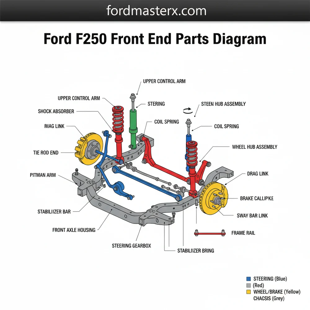
Ford F250 Front End Parts Diagram: Complete Guide
This Ford F250 front end parts diagram illustrates the comprehensive assembly of the steering linkage, suspension components, and axle housing. It provides a detailed layout of tie rods, drag links, and ball joints, helping owners understand the structural configuration of their heavy-duty truck’s steering system for easier maintenance and part identification.
📌 Key Takeaways
- Provides a visual map of the entire steering and suspension system
- Crucial for identifying tie rod ends and ball joints during repair
- Always support the vehicle with heavy-duty jack stands before inspection
- Use the diagram to cross-reference OEM part numbers before purchasing
- Ideal for troubleshooting loose steering or uneven tire wear
Understanding the complexity of a heavy-duty suspension system is the first step toward successful vehicle maintenance or repair. For truck owners and DIY mechanics, having access to an accurate ford f250 front end parts diagram is essential for identifying specific wear items and understanding how the various steering and suspension elements interact. This visual schematic serves as a roadmap for the vehicle’s chassis, illustrating the relationship between the steering gear, the axle, and the wheels. By studying the diagram, you will gain a clear overview of the system’s layout, learn how to diagnose common mechanical failures, and discover the correct sequence for replacing critical components to ensure your truck remains safe and stable on the road.
Deep Dive into the Front End Component Structure
The front-end assembly of a heavy-duty truck like the F250 is a sophisticated piece of engineering designed to handle immense weight and torque. When viewing a ford f250 front end parts diagram, the layout is typically divided into two primary sub-systems: the steering linkage and the suspension support. The steering linkage is responsible for translating the driver’s input from the steering wheel to the tires, while the suspension system manages the load and absorbs road impacts.
In a standard 4WD configuration, the diagram highlights several key components. At the heart of the steering system is the Pitman arm, which connects to the steering box. This arm moves the drag link, which in turn moves the tie rod assembly. The tie rods are the adjustable links that set the vehicle’s toe-in alignment and connect directly to the steering knuckles. The knuckles are the pivot points where the wheels are mounted, held in place by upper and lower ball joints. These joints are critical wear items; they allow the wheels to turn left and right while the suspension moves up and down.
The suspension layout also includes the track bar, a heavy-duty rod that prevents the front axle from moving laterally (side-to-side) under the frame. On many models, you will also see the steering stabilizer, which looks like a small horizontal shock absorber. Its role is to dampen vibrations and prevent the steering wheel from jerking when the tires hit a pothole. Understanding this blueprint is vital because a failure in one component, such as a worn track bar bushing, can place excessive stress on the tie rods and drag link, leading to a cascade of mechanical issues.
Ford F250 Front End Schematic: Identifying Steering Linkage, Ball Joints, and Suspension Stabilization Components
Step-by-Step Guide: How to Read and Use the Ford F250 Front End Parts Diagram
Interpreting a technical schematic can feel overwhelming at first glance, but following a systematic approach makes the process manageable. Whether you are performing a routine inspection or preparing for a major rebuild, use the following steps to navigate the front-end system effectively.
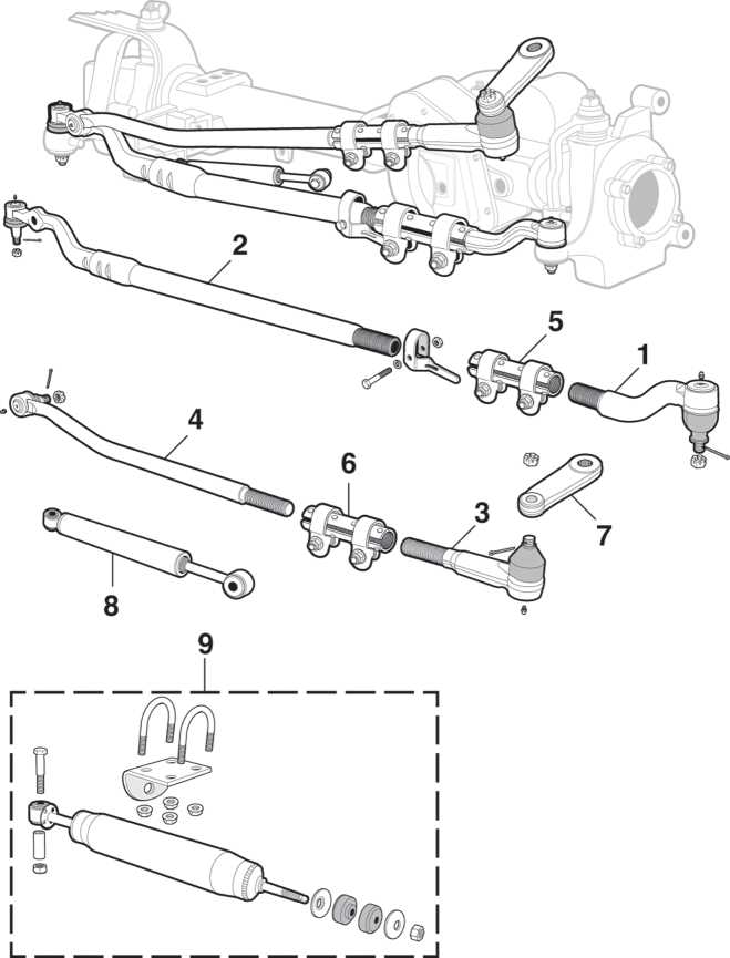
Most diagrams use a numbering system that corresponds to a parts list. Always cross-reference the number on the drawing with the OEM part number to ensure you are purchasing the correct component for your specific Gross Vehicle Weight Rating (GVWR).
- Orient the Perspective: Most diagrams provide a “driver-side” or “front-facing” view. Identify the steering gear box first, as this is the starting point of the steering system. Once you find the gear box, you can trace the movement outward toward the wheels.
- Locate the Primary Links: Follow the path from the Pitman arm to the drag link. The drag link is usually the longest bar that runs diagonally or horizontally across the front end. In your diagram, identify where the drag link connects to the passenger-side knuckle or the tie rod assembly.
- Identify the Pivot Points: Look for the upper and lower ball joints. These are typically represented as circular icons or joints connecting the steering knuckle to the axle “C” or control arms. Checking these in the diagram helps you understand how the wheel hub is secured.
- Trace the Stabilization System: Find the track bar and the steering stabilizer. The track bar is a critical safety component; in the schematic, note its mounting points on the frame and the axle. If these mounts are loose, the entire front end will feel unstable.
- Verify Hardware and Bushings: A comprehensive blueprint will also show smaller components like grease zerk fittings, cotter pins, and bushings. Ensure you identify every rubber or polyurethane component, as these are the most likely parts to degrade over time.
- Compare with the Physical Vehicle: With the diagram in hand, go under the truck and locate each part. Use a paint pen to mark components as you identify them. This physical verification ensures that what you see on the screen or paper matches the actual configuration of your F250.
Before inspecting or working on the front end, ensure the vehicle is on level ground with the parking brake engaged. If you lift the truck, always use heavy-duty jack stands rated for the F250’s weight. Never rely solely on a floor jack.
Common Issues and Troubleshooting with the Diagram
The ford f250 front end parts diagram is an invaluable tool when troubleshooting the infamous “death wobble”—a violent shaking of the steering wheel and front axle. By looking at the system layout, you can systematically check for play in the most common culprits.
One frequent problem is wear in the track bar bushing or the ball joint at the end of the track bar. In the schematic, this rod is what keeps the axle centered. If you notice lateral movement when someone turns the steering wheel while the truck is stationary, the diagram helps you locate exactly which bolt or bushing needs replacement. Another common issue is “loose” steering, which is often caused by worn tie rod ends. The diagram allows you to identify the inner and outer tie rods, which are the points most prone to developing “slop.”
Watch for uneven tire wear, such as cupping or feathering. This usually indicates that the ball joints (shown as the vertical pivots in your diagram) have failed, or that the shocks have lost their damping ability. If you hear a loud clunking sound when driving over bumps, reference the stabilizer bar links and bushings in your blueprint; these small components are often the source of annoying front-end noises.
Tips and Best Practices for Maintenance
Maintaining the front end of a heavy-duty truck requires more than just occasional inspections. Following industry best practices will extend the life of your components and save you money in the long run.
Always choose greasable aftermarket parts over “sealed-for-life” factory units if you use your truck for towing or off-roading. Adding fresh grease every oil change flushes out contaminants and significantly reduces friction wear.
- ✓ Use High-Quality Components: When replacing parts found on your diagram, opt for heavy-duty or “problem solver” series parts. These often feature larger ball studs and better sealing boots than standard replacements.
- ✓ Check Torque Specifications: Every bolt in the front-end system has a specific torque requirement. Refer to your service manual alongside the parts diagram to ensure components like the track bar bolt (which often requires over 400 ft-lbs) are tightened correctly.
- ✓ Perform a Dry Park Test: With the engine off and the truck on the ground, have an assistant turn the steering wheel back and forth while you watch the components listed in the diagram. Any popping or visible movement in the joints indicates a need for replacement.
- ✓ Alignment After Repair: Any time you replace a part shown in the steering linkage portion of the blueprint, you must have a professional alignment performed. Even a slight change in tie rod length can ruin a set of tires in a few hundred miles.
Maintaining the structural integrity of your truck’s chassis is a continuous process. By utilizing a comprehensive ford f250 front end parts diagram, you empower yourself to diagnose issues early, understand the internal mechanics of your vehicle, and perform repairs with confidence. Whether you are replacing a single tie rod end or performing a complete front-end overhaul, the clarity provided by a detailed schematic ensures that your F250 remains a reliable workhorse for years to come. Professional-grade maintenance starts with professional-grade information, and having the right diagram is the foundation of that success.
Frequently Asked Questions
Where is the steering box located?
The steering box is located on the driver-side frame rail. From here, the pitman arm connects to the drag link, which links to the passenger side steering knuckle. This setup forms the primary steering structure that transfers your input from the steering wheel directly to the front tires for control.
What does a front end parts diagram show?
A Ford F250 front end parts diagram shows the spatial relationship between steering and suspension components. It highlights how the drag link, tie rods, track bar, and shocks interact. Understanding this system configuration is essential for diagnosing death wobble, alignment issues, or general front-end clunking noises during operation.
How many major steering connections does an F250 have?
The standard steering linkage consists of four main ends: two on the tie rod and two on the drag link. Additionally, the track bar connects the axle to the frame at two points. Each knuckle also features an upper and lower ball joint, totaling four major pivoting connections per axle.
What are the symptoms of a bad front end component?
Common symptoms of failing front-end components include ‘death wobble,’ excessive steering wheel play, and uneven tire wear. You might also hear clunking sounds over bumps or experience the truck pulling to one side. A visual diagram helps pinpoint which specific component, such as a tie rod, has likely failed.
Can I replace front end parts myself?
Many front-end repairs are DIY-friendly if you have the right tools, like a ball joint press or tie rod puller. However, because the F250 is a heavy-duty truck, parts are heavy and bolts require high torque. Always perform a professional alignment after replacing any steering or suspension components.
What tools do I need for front end work?
You will need a heavy-duty jack and stands, a torque wrench capable of 150+ lb-ft, a pickle fork or puller set, and a comprehensive socket set. A grease gun is also necessary if you are installing aftermarket components that feature zerk fittings for regular maintenance and lubrication of the joints.


