Ford F150 Starter Wiring Diagram: Easy Setup Guide
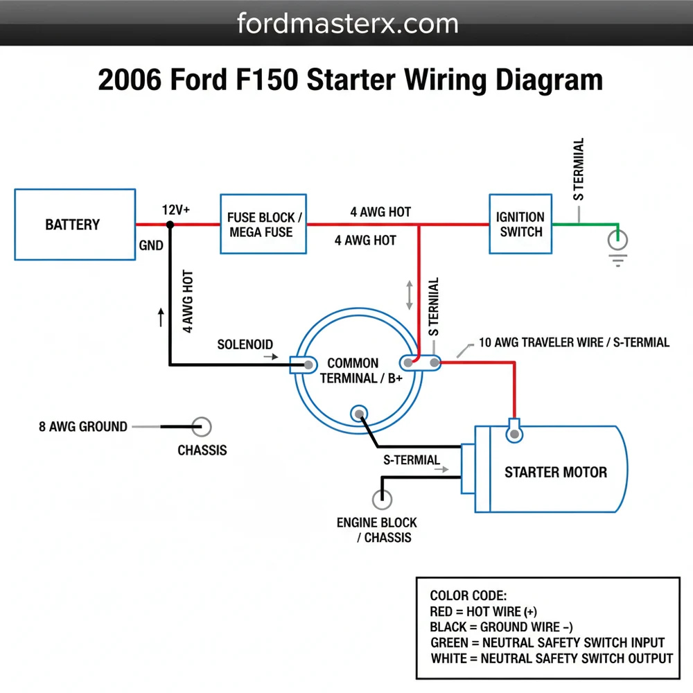
The 2006 Ford F150 starter circuit links the battery, ignition switch, and starter solenoid. A heavy-gauge hot wire connects the battery to the starter’s common terminal. When the ignition is turned, a signal travels through the neutral wire safety switch to engage the solenoid, completing the circuit to the ground wire for engine cranking.
📌 Key Takeaways
- Identifies the flow of current from the battery to the starter solenoid
- Helps locate the specific signal wire and high-amperage power cables
- Ensures the neutral safety switch circuit is correctly integrated for safety
- Provides a visual map for troubleshooting intermittent clicking or no-start issues
- Essential for verifying solid ground connections to the engine block
Troubleshooting a non-starting vehicle can be a daunting task, especially when dealing with the heavy-duty electrical demands of a full-size pickup. Having access to a clear and accurate 2006 Ford F150 starter wiring diagram is essential for identifying whether your “no-start” condition is caused by a dead battery, a faulty solenoid, or a break in the signal circuit. This diagram serves as a visual roadmap, detailing how current flows from the battery to the ignition switch and ultimately to the starter motor. In this article, you will learn how to identify specific wire colors, understand terminal designations, and follow the proper wiring sequence to restore your truck’s reliability.
The 2006 Ford F150 utilizes a high-torque, permanent-magnet starter motor. The electrical system relies on a consistent 12.6V voltage reading from the battery to engage the solenoid effectively.
Understanding the 2006 Ford F150 Starter Wiring Components
The wiring architecture for the 2006 Ford F150 starter system is designed to handle immense current while maintaining a safe control circuit. The primary “hot wire” is a heavy-duty, low-gauge cable (typically 2-gauge or 4-gauge) that runs directly from the positive battery terminal to the B-terminal on the starter solenoid. This terminal is often referred to as the common terminal because it provides the constant power needed for the motor to spin once the solenoid is engaged.
A secondary, thinner wire known as the traveler wire or trigger wire connects to the S-terminal (Start terminal) on the solenoid. In most 2006 F150 models, this wire is color-coded as Red with a Light Blue stripe. This wire only carries current when the ignition key is turned to the “Start” position. The diagram also illustrates the path through the Central Junction Box (CJB), where the starter relay and Fuse 101 (30A) reside. If the relay does not click, the break in the circuit is likely located before the starter motor itself.
The grounding system is equally vital. Unlike many household electronics that use a dedicated green neutral wire, the F150 uses the engine block and chassis as the primary ground wire path. The starter is grounded through its mounting bolts directly to the engine transmission housing. Any rust or debris on these mounting surfaces can create resistance, leading to a slow crank or a total failure of the electrical loop.
[DIAGRAM_PLACEHOLDER: 2006 Ford F150 Starter Wiring Diagram showing Battery, Starter Relay, Ignition Switch, and Starter Motor Solenoid with color-coded Red/Blue Traveler wire and Heavy Red Hot wire connections]
Step-by-Step Guide to Interpreting and Installing Starter Wiring

Reading an automotive diagram requires a systematic approach. By following the wiring sequence below, you can ensure that every connection meets the manufacturer’s specifications for safety and performance.
- ✓ Step 1: Identify the Main Battery Lead – Locate the thickest cable in the harness. This is the hot wire that delivers 12V directly from the battery. On the starter solenoid, this attaches to the largest threaded stud, usually secured with a heavy-duty brass screw or nut.
- ✓ Step 2: Locate the S-Terminal Connection – Find the smaller traveler wire (Red/Light Blue). This wire signals the solenoid to close the internal contactor. It connects to the smaller “S” terminal stud. Ensure the terminal connector is clean and tight to prevent intermittent starting issues.
- ✓ Step 3: Verify the Ground Path – Inspect the area where the starter motor meets the engine. This is your ground wire equivalent. If you see significant corrosion, use a wire brush to clean the mating surfaces to ensure a low-resistance return path for the current.
- ✓ Step 4: Check the Digital Transmission Range (DTR) Sensor – The diagram shows that the traveler wire passes through the DTR sensor (neutral safety switch). If the truck is not in Park or Neutral, the circuit remains open, and the traveler wire will not receive voltage.
- ✓ Step 5: Test Voltage at the Solenoid – Using a multimeter, check for 12V at the common terminal constantly. Then, have an assistant turn the key to “Start” while you check for voltage at the traveler wire. This confirms if the signal is reaching the motor.
- ✓ Step 6: Secure Connections – Once the wires are positioned according to the diagram, tighten all nuts. Be careful not to over-torque the brass screw on the solenoid, as the plastic housing can crack, leading to internal short circuits.
Always disconnect the negative battery terminal before working on the starter wiring. The “hot wire” at the starter is unfused and direct from the battery; touching it to the frame with a wrench will cause an immediate, high-current electrical arc and potential injury.
Tools and Materials Needed
To properly execute the wiring based on the 2006 Ford F150 starter wiring diagram, you will need a basic socket set (specifically 8mm, 10mm, and 13mm), a digital multimeter for voltage testing, a wire brush for cleaning terminals, and dielectric grease to prevent future corrosion. If you are replacing damaged wires, ensure you use the correct gauge to handle the high amperage—using a wire that is too thin will cause it to overheat and fail.
Common Issues & Troubleshooting the Starter Circuit

Even with a perfect diagram, real-world variables like heat and vibration can cause issues. One of the most frequent problems owners encounter is the “single click” sound. This usually indicates that the traveler wire is successfully activating the solenoid, but the common terminal is not receiving enough amperage to turn the motor, or the motor’s internal brushes are worn out.
Another common failure point in the 2006 F150 is the starter relay located in the passenger-side kick panel. If you turn the key and hear nothing at all, the diagram helps you trace the circuit back from the solenoid to the relay. You can test the relay by swapping it with an identical one (like the horn relay) to see if the engine cranks.
If your truck won’t start, try shifting the gear lever to ‘Neutral’ and then back to ‘Park.’ This can sometimes reseat a finicky Neutral Safety Switch, allowing the traveler wire to complete its circuit.
Warning signs of failing wiring include charred insulation on the hot wire, a “melted” smell after attempting to start, or visible green corrosion (copper oxide) on the brass screw terminals. If you see these signs, the wiring itself must be replaced or cleaned immediately to avoid a fire hazard. If voltage tests show power is reaching the S-terminal but the motor doesn’t react, the starter itself has likely reached the end of its service life.
Tips & Best Practices for Electrical Maintenance
When working with the 2006 Ford F150 starter wiring diagram, longevity is the goal. Automotive environments are harsh, with constant exposure to road salt, moisture, and engine heat. To ensure your repair lasts, always apply a thin layer of dielectric grease to all electrical connections. This grease does not conduct electricity but seals the connection against moisture, preventing the “green crust” that leads to high resistance.
Maintenance recommendations include checking your battery terminals every six months. A loose or corroded battery terminal can mimic a starter failure by dropping the voltage significantly under load. When purchasing replacement parts, avoid the cheapest “white-box” starters. Higher-quality units use better copper windings and more durable brass screw hardware, which are less likely to strip or fail under the high-torque demands of the 4.6L or 5.4L engines found in the 2006 model year.
Finally, consider the heat shield. The F150 starter is positioned relatively close to the exhaust manifold. If your diagram-guided installation is missing the factory heat shield, it is wise to install an aftermarket reflective wrap. Heat increases electrical resistance; by keeping the starter and its hot wire cool, you ensure maximum cranking speed and reduce the strain on your battery during the hot summer months.
Understanding the 2006 Ford F150 starter wiring diagram is more than just knowing where the wires go—it is about understanding the relationship between voltage, resistance, and mechanical engagement. By following the color codes and terminal identifications provided in this guide, you can confidently diagnose and repair your truck’s starting system, ensuring that it fires up reliably every time you turn the key.
Frequently Asked Questions
Where is the starter located?
The starter on a 2006 Ford F150 is located on the passenger side of the engine, where the transmission meets the block. It is tucked behind the wheel well liner, requiring you to access it from underneath the vehicle. Ensure the ground wire is disconnected before attempting to locate or remove the unit.
What does this wiring diagram show?
This 2006 Ford F150 starter wiring diagram illustrates the flow of current from the battery to the ignition switch and starter motor. It highlights the traveler wire paths that bridge the relay and the solenoid, ensuring the hot wire provides sufficient amperage to the common terminal for a successful engine start.
How many wires does the starter have?
The starter features three primary connections: the heavy-gauge hot wire from the battery, a smaller signal wire from the ignition (often called the traveler wire in generic diagrams), and a ground wire established via the mounting bolts. Some models include a dedicated neutral wire loop through the safety switch to prevent starting in gear.
What are the symptoms of a bad starter?
A failing starter typically manifests as a single loud click or a rapid chattering sound when turning the key. If the common terminal or ground wire is corroded, you may experience intermittent starting. A total failure means no response from the engine, even if the battery and hot wire are functional.
Can I replace this myself?
Yes, replacing a starter is a manageable DIY task for most Ford F150 owners. You will need to secure the vehicle on jack stands and disconnect the battery to avoid sparking the hot wire. Having a 2006 Ford F150 starter wiring diagram handy ensures you reconnect the signal and neutral wire leads correctly.
What tools do I need for this task?
To perform this task, you need a basic socket set (specifically 8mm, 10mm, and 13mm), an extension bar, and a multimeter to test voltage. A wire brush is helpful for cleaning the common terminal and ground wire connections to ensure a solid electrical bond for the starter motor.


