Ford F150 Radio Wiring Diagram: Easy Setup Guide
The 1998 Ford F150 radio wiring diagram maps out connections for power and speakers. The constant hot wire provides battery memory, while the ground wire attaches to the common terminal. Understanding how each traveler wire carries signals to speakers ensures a clean installation without shorting the neutral wire equivalent in the chassis ground.
📌 Key Takeaways
- Identify the light green/purple hot wire for constant 12V power.
- Locate the black/light green ground wire to complete the circuit.
- Ensure the common terminal is securely bonded to the vehicle chassis.
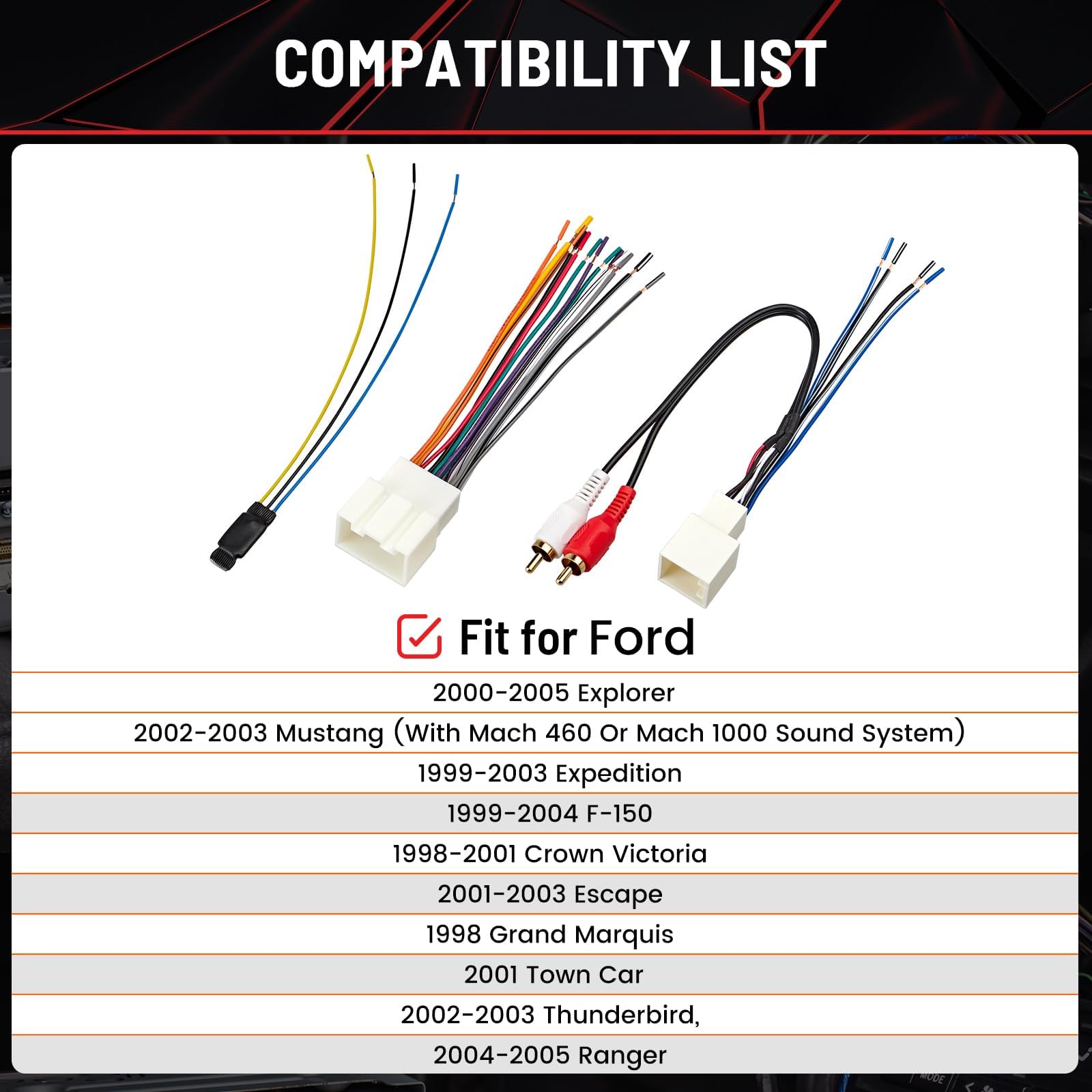
- Use a wiring harness adapter to avoid cutting factory plugs.
- Use this diagram when troubleshooting audio loss or installing new head units.
Upgrading the audio system in a classic tenth-generation pickup requires precision, and having a reliable 1998 ford f150 radio wiring diagram is the first step toward a successful installation. Whether you are replacing a malfunctioning factory head unit or installing a modern touchscreen interface with smartphone integration, understanding the specific wire colors and pin locations is essential. This guide provides a comprehensive breakdown of the electrical signals behind your dashboard, ensuring that every connection—from the main power supply to the individual speaker outputs—is handled with professional-grade accuracy. By following this detailed wiring map, you can avoid the frustration of blown fuses or damaged electrical components, allowing you to focus on achieving the best possible sound quality in your truck.
Decoding the 1998 Ford F150 Radio Wiring Diagram
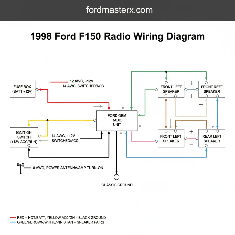
The electrical architecture of the 1998 Ford F150 radio system is relatively straightforward compared to modern data-bus systems, but it still requires careful attention to detail. The factory setup typically involves two main connectors: one for power and ground, and another for the speaker signals. When looking at the 1998 ford f150 radio wiring diagram, you will notice that Ford utilized a specific color-coding scheme that remains consistent across most F-series models of that era.
To understand the diagram, you must identify the primary power leads. The “hot wire” in this system is usually a constant 12V feed that maintains your radio’s memory settings, such as clock time and preset stations. This is distinct from the switched power wire, which only receives current when the ignition is in the “on” or “accessory” position. Unlike a household circuit where you might find a traveler wire or a neutral wire, automotive DC systems rely on a chassis ground wire to complete the circuit.
In the diagram below, the pinouts are organized to help you identify the common terminal points for each function. Note that while some high-end trims might have an external amplifier, the standard 1998 model uses high-level outputs directly from the head unit.
Main Power Connector (Rectangular):
Pin 1: Light Green/Purple -> Constant 12V (Hot Wire)
Pin 2: Black/Light Green -> Ground Wire
Pin 3: Pink/Black -> Switched 12V (Ignition)
Pin 4: Blue/Red -> Dimmer/Illumination
Pin 5: Black -> Chassis Ground (Common Terminal)
Speaker Connector (Square):
Pin 1: White/Light Green -> Front Left Speaker (+)
Pin 2: Dark Green/Orange -> Front Left Speaker (-)
Pin 3: White/Red -> Front Right Speaker (+)
Pin 4: Brown -> Front Right Speaker (-)
Pin 5: Tan/Yellow -> Rear Left Speaker (+)
Pin 6: Gray/Light Blue -> Rear Left Speaker (-)
Pin 7: Orange/Red -> Rear Right Speaker (+)
Pin 8: Black/White -> Rear Right Speaker (-)
Always verify the voltage of each wire with a multimeter before making permanent connections. In older vehicles like the 1998 F150, wire colors can sometimes fade or appear different under shop lighting, so testing for continuity and 12V power is a critical safety step.
Step-by-Step Guide to Installation and Interpretation
Reading a 1998 ford f150 radio wiring diagram is one thing; applying it to your truck is another. To ensure a clean installation that lasts for years, follow these sequential steps. This process ensures that you maintain the integrity of the vehicle’s electrical system while providing a stable platform for your new audio equipment.
- Disconnect the Battery: Before touching any wiring behind the dash, disconnect the negative terminal of your battery. This prevents accidental shorts that could blow the main fuses or damage the vehicle’s ECU.
- Remove the Factory Radio: Use Ford-specific radio removal tools (often called U-shaped DIN tools). Insert them into the holes on the side of the radio faceplate until they click, then pull the unit forward.
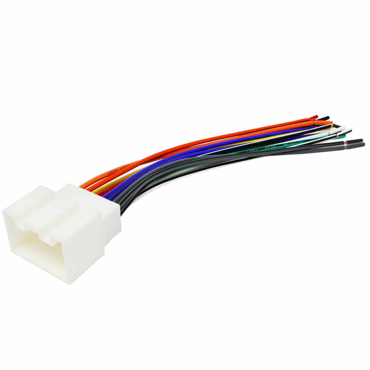
- Identify the Harness: Once the radio is out, you will see two plastic connectors. Match the wire colors on these connectors to your 1998 ford f150 radio wiring diagram. If the factory harness has been cut by a previous owner, you will need to identify each wire by its function using a digital multimeter.
- Prepare the New Harness: It is highly recommended to use an aftermarket wiring adapter. This allows you to solder the new radio’s wires to the adapter on a workbench rather than inside the cramped dashboard. Match the “hot wire” of the radio (usually yellow) to the constant power wire of the truck, and the “ground wire” (usually black) to the truck’s ground.
- Connect the Speakers: Follow the diagram to connect the positive and negative leads for all four speakers. Maintaining correct polarity is essential; if you swap the positive and negative on one speaker, it will be “out of phase,” resulting in a significant loss of bass response.
- Insulate Connections: Use heat-shrink tubing or high-quality electrical tape for every connection. In an automotive environment, vibration can cause loose wires to touch, creating a fire hazard or short circuit.
- Test the Voltage: Before sliding the new radio into the dash, reconnect the battery and turn the ignition to the “ACC” position. Ensure the radio powers on and that all speakers are functioning correctly.
Do not confuse automotive wiring with residential electrical systems. While a house uses a neutral wire and potentially a brass screw for grounding on an outlet, a truck uses the metal frame as the return path. Never attempt to use household wire nuts or solid-core gauge wire in a vehicle, as they are not designed for the vibrations of the road.
To perform this job correctly, you will need several basic tools. A standard 18-gauge or 16-gauge wire is typically used for the power and speaker leads. Using the wrong wire gauge can lead to excessive resistance and heat. Additionally, a multimeter is vital for checking the voltage across the constant and switched lines. Ensure your ground connection is secured to a clean, unpainted metal surface—this is your common terminal for the entire audio system.
Common Troubleshooting Scenarios
Even with a perfect 1998 ford f150 radio wiring diagram, you may encounter obstacles. The age of the 1998 F150 means that factory wiring may have become brittle, or previous “backyard” repairs might have altered the original configuration.
One frequent issue is the radio not turning on despite all connections appearing correct. This is often due to a blown fuse in the interior fuse panel (usually located under the dashboard on the driver’s side). Check the fuses related to the “Cigar Lighter” or “Radio Accessory” circuits. Another common problem is a “whining” noise that increases with engine RPM. This is usually caused by a poor ground wire connection. In these cases, the diagram helps you locate the common terminal point where the ground is anchored, allowing you to clean the contact point or relocate it to a better chassis ground.
If you find that your radio loses its programmed settings every time you turn off the truck, you have likely swapped the constant hot wire with the switched ignition wire. Refer back to the diagram to ensure the memory wire is connected to the constant 12V source.
If the factory wire colors don’t match your diagram exactly, look for the “tracer” color—the thin stripe on the wire. Ford often uses a base color with a contrasting stripe to distinguish between positive and negative speaker leads.
Maintenance and Best Practices for Ford Audio Systems
When working with the 1998 ford f150 radio wiring diagram, longevity should be your goal. The interior of a truck experiences extreme temperature fluctuations and constant vibration. To ensure your audio system remains reliable, follow these best practices:
- ✓ Use a Wiring Harness Adapter: Avoid cutting the factory plugs whenever possible. An adapter preserves the vehicle’s resale value and makes future upgrades much easier.
- ✓ Solder Your Connections: While crimp connectors are faster, soldering provides a superior mechanical and electrical bond that won’t vibrate loose over time.
- ✓ Secure the Wiring: Use zip ties to bundle the excess wire behind the dashboard. This prevents wires from rattling against the plastic or getting snagged by the heater core controls.
- ✓ Check the Antenna Cable: The 1998 F150 uses a standard Motorola-style antenna plug. Ensure it is seated deeply into the new radio; a loose antenna can result in poor AM/FM reception and “static” noise.
Regarding cost-saving, while it may be tempting to buy the cheapest head unit available, investing in quality components pays off in the long run. High-quality wire with the correct gauge thickness ensures that the voltage reaches your speakers without drop-off, providing a crisper sound. If you are adding a powerful aftermarket amplifier, you may need to run a dedicated heavy-gauge hot wire directly from the battery to the cabin, as the factory radio wiring is not designed to handle high-amperage loads.
In conclusion, having a clear and accurate 1998 ford f150 radio wiring diagram is the foundation of any successful truck audio project. By identifying the ground wire, constant hot wire, and specific speaker leads, you can perform an installation that looks and sounds professional. Remember to prioritize safety by disconnecting the battery and double-checking your connections with a multimeter. With the right preparation and the details provided in this guide, your 1998 Ford F150 will be ready for many more miles of high-quality audio performance.
Frequently Asked Questions
Where is the radio wiring harness located?
The radio wiring harness is located directly behind the center dashboard trim panel. After removing the trim around the head unit, you will find the factory connectors plugged into the rear of the radio. These connectors house all the necessary power, ground, and speaker signal wires for the audio system.
What does the radio wiring diagram show?
The 1998 Ford F150 radio wiring diagram illustrates the electrical path from the battery to the speakers. It identifies color-coded wires, such as the hot wire for constant power and the common terminal for grounding, helping you avoid damaging your vehicle’s sensitive electrical components during a stereo installation.
How many wires does the F150 radio harness have?
A standard 1998 Ford F150 setup typically utilizes two primary connectors. One handles power and ground, including the constant hot wire and illumination leads. The other acts as a traveler wire hub for the four speakers, totaling about 16 to 24 individual pin connections depending on the specific trim level.
What are the symptoms of a bad radio wiring connection?
Symptoms of a bad radio wiring setup include frequent fuse blows, intermittent power loss, or static in the speakers. If the ground wire is loose or the hot wire is pinched, the radio may reset unexpectedly. Proper use of a wiring diagram prevents these common terminal connection errors.
Can I install an aftermarket radio myself?
Yes, replacing a radio is a popular DIY project for F150 owners. Using a wiring diagram allows you to safely match aftermarket wires to factory colors. However, care must be taken when identifying the neutral wire equivalent or ground to prevent short circuits that could damage the dash electronics.
What tools do I need for radio wiring?
You will need a set of trim removal tools to pop the dash bezel without scratching it. Additionally, a multimeter helps verify the hot wire, while wire strippers and crimp connectors are essential for securing the traveler wire connections to your new aftermarket radio harness or the common terminal.


