Ford F150 MAP Sensor Location Diagram: Quick Guide
The Ford F150 MAP sensor location is typically on the top or rear of the intake manifold, behind the throttle body. It monitors manifold pressure for the ECU to regulate fuel. Use an OBD-II scanner to verify a diagnostic code before removal to ensure the sensor is failing.
📌 Key Takeaways
- Identifies the precise placement of the MAP sensor on the intake plenum
- Distinguishes the MAP sensor from other nearby vacuum-related components
- Helps diagnose air-fuel mixture issues and rough idling problems
- Essential for locating the sensor without removing unnecessary engine parts
- Used primarily when a check engine light indicates manifold pressure faults
Finding the exact diagram ford f150 map sensor location is a critical first step for any truck owner facing a rough idle, poor fuel economy, or a persistent check engine light. The Manifold Absolute Pressure (MAP) sensor is a vital component that monitors the air pressure entering your engine, providing real-time data to the Engine Control Unit (ECU). Without an accurate reading from this sensor, your truck’s computer cannot calculate the correct amount of fuel to inject, leading to significant performance issues. This guide provides a detailed visual and descriptive breakdown of where this sensor is tucked away across different engine configurations, ensuring you can perform diagnostics or replacements with confidence.
The MAP sensor location varies significantly between the 5.0L V8 Coyote engine and the twin-turbocharged EcoBoost variants. Always verify your specific engine displacement before beginning the search under the hood.
Understanding the Ford F150 MAP Sensor Diagram
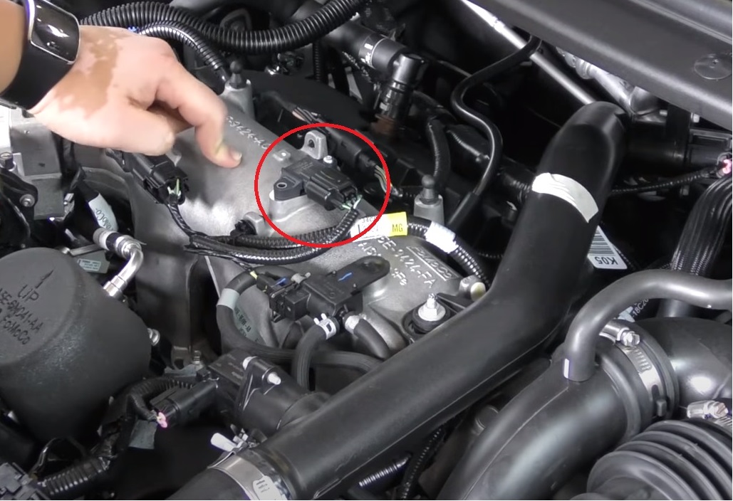
The MAP sensor is a compact electronic device typically secured by one or two small bolts or a locking clip. To interpret the diagram ford f150 map sensor location correctly, you must first identify the primary landmarks within the engine bay. In most configurations, the sensor is situated directly on the intake manifold, which is the large plastic or metal housing sitting on top of the engine block. Because the sensor needs to measure the internal vacuum and pressure of the intake tract, it is always placed behind the throttle body but before the air enters the cylinder heads.
On the 3.5L and 2.7L EcoBoost engines, the diagram often shows two similar-looking sensors. One is the Throttle Inlet Pressure (TIP) sensor, located on the plastic piping before the throttle body, while the true MAP sensor is located further back, directly on top of the intake manifold plenum. For the 5.0L V8 engine, the sensor is often found at the very rear of the intake manifold, tucked closely against the firewall. This location can be difficult to see from the front of the truck, requiring you to reach over the engine or use a mirror to verify its position.
The diagram also highlights the electrical connector, which usually features a three-wire or four-wire harness. This harness sends a 5-volt reference signal back to the ECU. Understanding the surrounding components is equally important; the sensor is generally situated away from the primary coolant flow lines but may be near the vacuum lines used for the brake booster or the EVAP system.
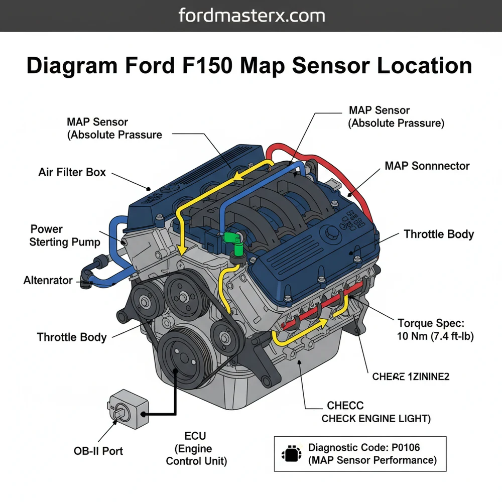
[DIAGRAM_PLACEHOLDER – A detailed overhead view of a Ford F150 engine bay. Labels point to the intake manifold. Label A: 5.0L V8 MAP Sensor Location (Firewall side). Label B: EcoBoost MAP Sensor Location (Center of Manifold). Label C: Throttle Body. Label D: ECU Wiring Harness Path.]
Step-by-Step Guide to Locating and Accessing the Sensor
Finding and accessing the sensor requires a methodical approach to ensure no sensitive plastic clips or vacuum lines are damaged during the process. Follow these steps to navigate the engine bay using the diagram ford f150 map sensor location as your primary reference.
- ✓ Step 1: Vehicle Preparation and Safety – Ensure the engine is completely cool to the touch. You will be working near areas that retain heat, such as the cylinder heads and rear manifold. Disconnect the negative battery terminal to prevent any electrical surges to the ECU while handling sensor connectors.
- ✓ Step 2: Identify Engine Type – Pop the hood and locate the engine emission sticker or the displacement badge on the engine cover. If you have an EcoBoost, look for the large plastic “EcoBoost” cover. If you have the 5.0L V8, you will see the distinct “Coyote” intake runners.
- ✓ Step 3: Remove the Engine Cover – Most F150 models use a plastic decorative cover secured by nuts or push-pins. Remove these to expose the top of the intake manifold. Be careful not to drop hardware into the accessory belt area.
- ✓ Step 4: Locate the Reference Landmarks – Find the throttle body (where the large air intake tube meets the engine). Move your eyes toward the rear of the engine. On EcoBoost models, the MAP sensor is usually right in the middle of the manifold. On V8 models, look toward the driver-side rear corner near the firewall.
- ✓ Step 5: Inspect the Connector – Once you spot the small rectangular sensor, look for the red or grey locking tab on the electrical connector. This is a key visual marker in any diagram ford f150 map sensor location guide.
- ✓ Step 6: Access and Removal – Use a small socket (typically 8mm or 10mm) or a Torx bit depending on the specific model year. Be extremely careful with the torque spec when reinstalling; these sensors bolt into plastic manifolds that can easily strip or crack.
Do not attempt to remove the sensor while the engine is running or immediately after driving. Heat from the coolant flow and exhaust manifolds can cause severe burns, and the plastic manifold is more prone to damage when hot.
Tools and Materials Needed
To complete this task, you will need a basic automotive toolkit. Having an OBD-II scanner is also highly recommended to clear any codes after the sensor is serviced.
- ✓ 1/4-inch drive ratchet and extension
- ✓ 8mm and 10mm deep-well sockets
- ✓ T20 or T25 Torx bit (engine dependent)
- ✓ Electrical contact cleaner or MAF/MAP sensor cleaner
- ✓ Flashlight or headlamp for rear-engine visibility
Common Issues & Troubleshooting

When the MAP sensor fails, it often triggers a specific diagnostic code through the OBD-II system. The most common codes include P0107 (Low Input) or P0108 (High Input). If you see these on your scanner, the diagram ford f150 map sensor location becomes your roadmap for repair. A failing sensor often manifests as “searching” for an idle, where the RPMs fluctuate wildly, or a noticeable “bogging” sensation during heavy acceleration.
In some cases, the sensor itself isn’t faulty, but rather the port it sits in is clogged with oil vapor or carbon deposits. This is particularly common in high-mileage EcoBoost engines where blow-by gases can coat the internal sensing element. Before replacing the part, many DIYers find success by cleaning the sensor with a specialized non-residue electronic cleaner. If the sensor is physically cracked or if the wiring harness shows signs of fraying near the accessory belt or other moving parts, a full replacement is necessary.
If you are getting MAP sensor codes but the sensor appears fine, check your vacuum lines for leaks. A small crack in a vacuum hose can mimic a sensor failure by providing inconsistent pressure readings to the ECU.
Tips & Best Practices for Maintenance
Maintaining the health of your Ford F150’s air induction system will prolong the life of the MAP sensor. One of the best ways to do this is to ensure you are using high-quality air filters and changing them at the recommended intervals. Debris that bypasses a low-quality filter can eventually contaminate the sensor. Additionally, if you have a modified truck with a cold air intake, ensure the sensor is seated correctly and that no moisture is entering the intake tract.
When installing a new sensor, pay close attention to the O-ring seal. A common mistake is allowing the old O-ring to stay stuck in the manifold, which prevents the new sensor from seating properly, leading to a vacuum leak. Apply a tiny amount of clean engine oil to the new O-ring to help it slide into place without pinching. Always adhere to the factory torque spec; for most MAP sensors, this is very low (around 2 to 5 Newton-meters). Over-tightening will almost certainly strip the plastic threads of the intake manifold, leading to an expensive and unnecessary repair.
Finally, if your truck is showing symptoms of power loss but the MAP sensor tests fine, consider checking related systems. A stretched timing chain or a failing fuel pump can sometimes cause the ECU to struggle with air-fuel calculations, leading to secondary codes that might confuse the diagnostic process. Using the diagram ford f150 map sensor location as a starting point allows you to rule out the simplest air-management components before moving on to more complex mechanical internal issues. Quality OEM sensors are always recommended over cheap aftermarket alternatives to ensure the calibration matches your truck’s factory ECU settings perfectly.
Frequently Asked Questions
Where is the MAP sensor located?
On most Ford F150 models, the MAP sensor is mounted directly onto the upper intake manifold, often toward the back of the engine. It is a small plastic component secured with one or two bolts, connected to the main wiring harness and sometimes a vacuum hose.
What does the MAP sensor diagram show?
The diagram illustrates the physical mounting point of the sensor relative to the throttle body and intake manifold. It also identifies the electrical connector and vacuum port, helping you visualize how the sensor interacts with the engine’s air intake system to provide data to the ECU.
How many wires does the MAP sensor have?
Most Ford F150 MAP sensors utilize a three-wire electrical connector. These wires provide a 5-volt reference signal, a ground, and a signal return that varies based on manifold pressure. Testing these wires with a multimeter can help determine if the sensor or the wiring harness has failed.
What are the symptoms of a bad MAP sensor?
A failing MAP sensor typically triggers a check engine light and stores a diagnostic code like P0107. You may notice poor fuel economy, engine hesitation under load, or a rough idle. Since the ECU relies on this data for timing, performance will be significantly degraded when it fails.
Can I replace this sensor myself?
Replacing the MAP sensor is a very common DIY task that requires only basic hand tools and about 15 minutes. By following a location diagram, you can easily access the sensor, unplug the electrical connector, and swap the unit out without needing a professional mechanic’s assistance.
What tools do I need for this task?
You will generally need a 1/4-inch drive socket set (typically 8mm or 10mm), a small flat-head screwdriver to release electrical tabs, and an OBD-II scanner to clear codes. Always ensure you follow the correct torque spec for the mounting bolts to prevent damage to the plastic manifold.