Ford F150 Gas Tank Diagram: Complete System Layout
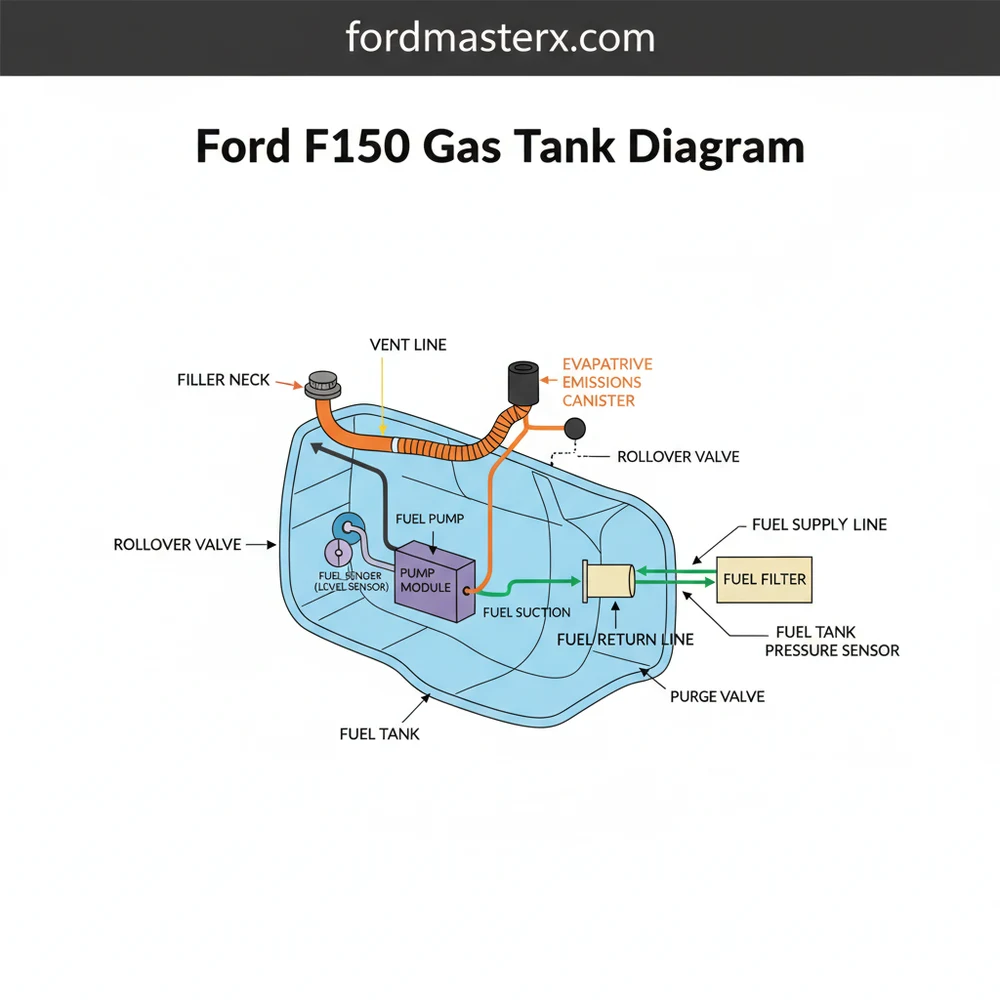
A Ford F150 gas tank diagram displays the internal and external layout of the fuel storage system, including the pump, filler neck, and vent lines. This configuration is essential for identifying mounting points and electrical connections when troubleshooting fuel delivery issues or performing a complete tank replacement.
📌 Key Takeaways
- Visualizes the spatial arrangement of fuel lines and mounting brackets.
- Identifying the fuel pump assembly location is critical for diagnostics.
- Always relieve fuel system pressure before working on any tank components.
- Use the diagram to verify the routing of evaporative emission lines.
- Essential for choosing the correct replacement tank size and configuration.
The Ford F-150 is the backbone of the American workforce, and for many DIY enthusiasts, maintaining this powerhouse is a point of pride. One of the most critical systems to understand for long-term reliability is the fuel delivery system. Whether you are dealing with a faulty fuel pump, a rusted fuel strap, or a persistent EVAP leak, having a clear understanding of the Ford F-150 gas tank diagram is essential. This guide provides a deep dive into the physical layout, electrical connections, and mechanical components of the F-150 fuel system, specifically focusing on the most common configurations found in the 12th (2009-2014) and 13th (2015-2020) generations.
Understanding the architecture of your truck’s fuel system allows you to diagnose issues without over-relying on expensive shop labor. Because the F-150 is offered in various cab and bed lengths, the fuel tank’s capacity and location can vary, but the fundamental components remain remarkably consistent. From the filler neck at the bedside to the fuel lines feeding the engine, every part plays a specific role in keeping your truck on the road.
Main Components and Features
The F-150 gas tank is more than just a hollow container. It is an integrated system designed to manage liquid fuel, pressurized vapors, and high-pressure delivery. Depending on your specific model, your tank may be constructed of high-density polyethylene (HDPE) plastic or galvanized steel. Here are the primary components found in a standard diagram:
- The Fuel Tank Body: F-150s typically feature three main sizes: the 23-gallon (standard), the 26-gallon, and the massive 36-gallon extended-range tank. The tank is usually mounted on the driver-side frame rail, extending from the rear of the cab toward the rear axle.
- Fuel Pump Assembly (Module): Located at the top of the tank, this is a “drop-in” unit. It contains the electric fuel pump, the primary fuel filter (strainer), and the pressure regulator.
- Fuel Level Sending Unit: Often integrated into the pump assembly, this consists of a float arm and a resistor. As the float moves with the fuel level, it changes the electrical resistance, which the truck’s computer translates into the gauge reading on your dashboard.
- Fuel Filler Neck: This is the tube that connects the exterior fuel door to the tank. Modern F-150s (2009+) utilize the “Easy Fuel” capless system, which features a spring-loaded flapper door instead of a traditional screw-on cap.
- EVAP (Evaporative Emission) Lines: These lines carry fuel vapors from the tank to the charcoal canister. This system prevents raw gasoline fumes from escaping into the atmosphere.
- Fuel Tank Straps: These are the heavy-duty metal bands that secure the tank to the chassis. They are common failure points in “rust-belt” states due to road salt accumulation.
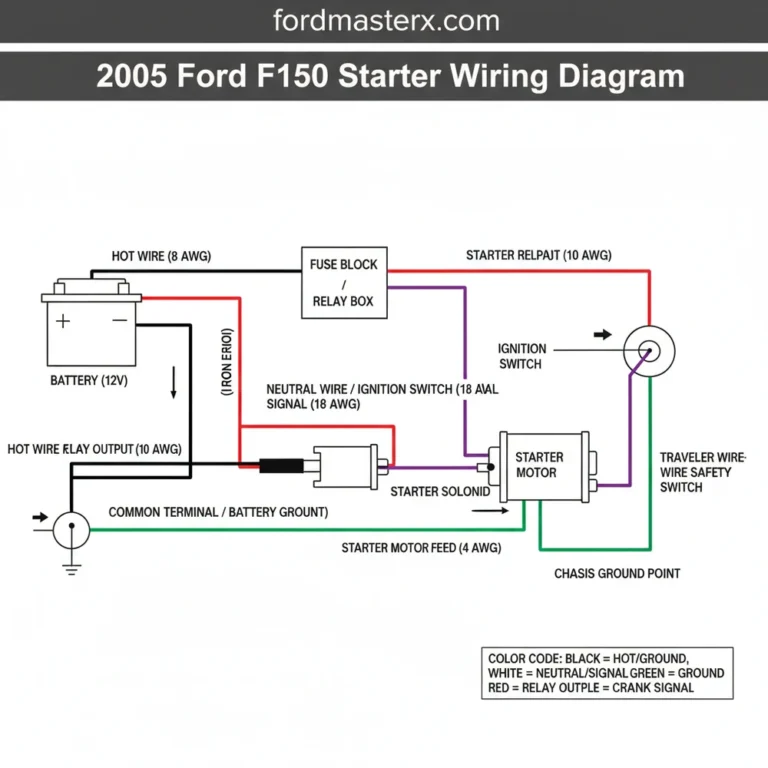
How to Read the Diagram and Identify Wiring

When looking at a Ford F-150 gas tank diagram, you are usually looking at a “top-down” or “exploded” view. The most confusing part for DIYers is often the electrical connector at the top of the fuel pump. For most F-150 models from 2004 to 2018, the fuel pump module uses a 4-pin or 6-pin connector.
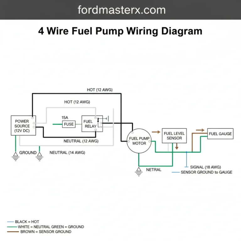
To read the wiring diagram correctly, you must identify the pinout. While colors can vary slightly by year, the standard Ford color coding for the fuel system is as follows:
- Pink/Black or Dark Green/White: This is typically the 12V power feed for the fuel pump motor.
- Black: This is the primary ground for the pump motor.
- Yellow/White: This is the signal wire for the fuel level sending unit (gauge).
- Blue/Orange: This is the reference ground for the sending unit.
Physically, the diagram will show the fuel lines exiting the top of the pump. Most F-150s use “Quick-Connect” fittings. These require specific tools or the compression of plastic tabs to release. On the diagram, you will see a “Supply Line” (which is usually 3/8″ or 5/16″ diameter) leading toward the engine and a “Vapor Line” leading to the EVAP canister located near the middle of the frame rail.
Installation and Removal Tips

Accessing the gas tank components on an F-150 can be done in two ways: by dropping the tank or by lifting/moving the truck bed. Most DIYers find dropping the tank easier if they have a floor jack, while those with a shop crane or several friends may prefer removing the bed bolts to access the pump from above.
Step 1: Drain the Tank. A gallon of gasoline weighs roughly 6 pounds. A 36-gallon tank nearly full weighs over 200 pounds, making it dangerous to handle. Drive the truck until the “Low Fuel” light comes on, or use a siphon pump to remove as much fuel as possible.
Step 2: Disconnect the Filler Neck. Before lowering the tank, loosen the hose clamps on the rubber neck connecting the fuel door to the tank. If you forget this, you risk tearing the neck or damaging the tank inlet.
Step 3: Support and Lower. Use a transmission jack or a floor jack with a wide piece of plywood to distribute the weight. Remove the two bolts holding the straps, and slowly lower the tank a few inches. This gives you enough room to reach over the top and disconnect the electrical harness and the fuel/vapor lines.
Troubleshooting Common Gas Tank Issues
If your F-150 is experiencing issues, the gas tank diagram helps you pinpoint where to test. Here are the most common failure modes and how to address them:
1. The “No Start” Condition: If the engine cranks but won’t fire, listen for the fuel pump. Turn the key to the “ON” position (without cranking). You should hear a 2-second hum from the tank area. If you hear nothing, check the Fuel Pump Driver Module (FPDM). On many F-150s (especially 2004-2013), this module is mounted on the frame crossmember above the spare tire. It is notorious for corroding and cracking, cutting power to the pump.
2. Erratic Fuel Gauge: If your gauge reads “Empty” despite having a full tank, or if the needle bounces, the problem is likely the sending unit float or the resistor card inside the tank. Use a multimeter to check the resistance between the Yellow/White wire and the Blue/Orange wire at the tank connector. A reading of roughly 15 ohms indicates a full tank, while 160 ohms indicates empty (values may vary slightly by generation).
3. Slow Fuel Filling (Clicking Off): If the gas pump at the station constantly clicks off while you are trying to fill up, there is a blockage in the EVAP system. Refer to your diagram to find the “Vapor Vent Line” and the charcoal canister. Often, the vent solenoid becomes stuck closed or the charcoal canister becomes saturated with liquid fuel (usually from “topping off” the tank), preventing air from escaping as fuel enters.
Final Maintenance Checks
Once you have utilized the diagram to complete your repairs, perform a “leak test.” Before fully tightening the tank straps and driving, prime the system by cycling the key several times to build pressure. Inspect the top of the fuel pump module for any signs of weeping or moisture around the quick-connect fittings.
For F-150 owners in coastal or snowy regions, applying a corrosion inhibitor to the fuel strap bolts and the fuel pump driver module mounting points can save hours of frustration in the future. By understanding the layout and electrical requirements of your gas tank, you ensure that your Ford F-150 remains the reliable workhorse it was designed to be.
Step-by-Step Guide to Understanding the Ford F150 Gas Tank Diagram: Complete System Layout
Identify the specific tank configuration and capacity for your F150 model.
Locate the fuel filler neck and vent line connections on the diagram.
Understand how the mounting straps and brackets secure the tank structure.
Disconnect the electrical harness and fuel lines from the pump assembly.
Verify that all EVAP system hoses are clear and properly routed.
Complete the installation by securing the tank and checking for leaks.
Frequently Asked Questions
Where is the fuel pump located?
The fuel pump component is located inside the gas tank assembly, typically accessed from the top. In most Ford F150 models, you must either drop the tank from the chassis or remove the truck bed to reach the pump and its electrical wiring harness connector for repair or replacement.
What does the gas tank diagram show?
This diagram illustrates the complete structure of the fuel storage system. It highlights the main tank body, the fuel filler neck, vapor lines, the sending unit, and the mounting straps. It provides a visual guide for the layout of the entire evaporative emissions system and fuel delivery components.
How many vent lines does the gas tank have?
Most F150 system configurations feature two to three main vent and return lines. These include the primary filler vent, the vapor recovery line leading to the charcoal canister, and sometimes a separate return line depending on whether the specific fuel system is returnless or uses a traditional regulator.
What are the symptoms of a bad gas tank?
Common signs include fuel leaks puddling under the truck, a strong smell of gasoline, or difficulty filling the tank due to a clogged vent. Structural damage like rust or dents can also cause the fuel pump to fail prematurely or trigger check engine lights for various EVAP leaks.
Can I replace the gas tank myself?
Yes, replacing the tank is a manageable DIY project if you have the right tools and safety equipment. It involves draining the fuel, disconnecting lines, and unbolting the straps. However, the tank’s bulky size and weight usually make it a two-person job for safety and proper alignment.
What tools do I need for tank removal?
You will need a basic socket set, fuel line disconnect tools, a floor jack with a wood block for support, and safety gear. A siphon pump is also necessary to empty the tank, as a full gas tank is too heavy and dangerous to maneuver during the removal process.