Ford F150 Fuse Box Diagram: Easy Identification Guide
The Ford F150 fuse box diagram consists of two main panels: the passenger compartment fuse panel located under the dashboard to the left of the steering column, and the high-current power distribution box under the hood. These panels house critical fuses for the ECU, fuel pump, and various lighting circuits.
📌 Key Takeaways
- Identify internal and engine bay fuse locations easily
- ECU and fuel pump relays are the most critical components
- Always use the correct amperage to prevent electrical fires
- A test light is the best tool for checking fuse continuity
- Reference this diagram when electrical accessories lose power
The 1995 Ford F-150 remains one of the most iconic “Old Body Style” (OBS) trucks ever produced. For DIY enthusiasts and truck owners, maintaining the electrical integrity of this ninth-generation F-Series is crucial for both performance and safety. Central to this maintenance is understanding the 1995 Ford F150 fuse box diagram. Over decades of use, electrical components can fail, and often, the culprit is a simple blown fuse or a malfunctioning relay. This guide provides a comprehensive breakdown of the fuse locations, diagrams, and troubleshooting steps to help you keep your classic Ford on the road without expensive trips to the mechanic.
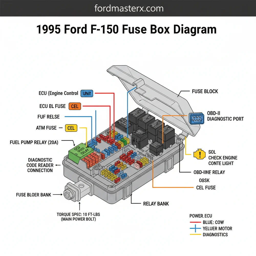
Main Components and Fuse Box Locations
The 1995 Ford F-150 utilizes a dual-system approach to electrical protection. Unlike modern vehicles that may have four or five different modules, the 1995 model simplifies things into two primary locations: the Interior Fuse Panel and the Engine Compartment Power Distribution Box. Knowing exactly where these are and what they house is the first step in any electrical repair.
1. The Interior Fuse Panel (Under-Dash): This panel is located inside the cab, to the left of the steering column. It is tucked behind a removable plastic cover near the driver’s left knee. This panel primarily handles low-amperage circuits related to the cabin experience—think instrument clusters, interior lighting, turn signals, and the radio. It uses standard “blade” type fuses (ATO/ATC), which are color-coded by amperage (e.g., Blue for 15A, Yellow for 20A).
2. The Power Distribution Box (Engine Bay): Located on the driver’s side fender apron, near the battery and the air filter housing, this box is the “heavy lifter” of the truck’s electrical system. It houses high-amperage “Maxi-fuses” and several critical relays. These components protect high-load circuits like the alternator, the fuel pump, the Engine Control (EEC) system, and the trailer towing package. The cover of this box is secured by plastic tabs and usually features a simplified map on the underside.
How to Use and Read the Fuse Box Diagram
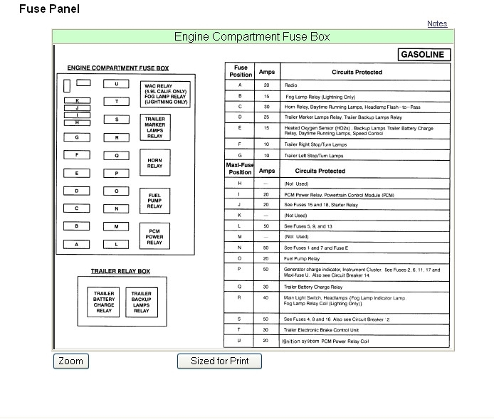
To effectively use the 1995 Ford F150 fuse box diagram, you must match the numbered slot in the box with the corresponding circuit description. Ford utilized a numerical grid system for these trucks. Below is a detailed breakdown of the most common fuse assignments found in the 1995 model year.
Interior Fuse Panel Breakdown
- Fuse 1 (15A): Turn signal flasher, back-up lamps.
- Fuse 2 (15A): Warning lamps, instrument cluster, electronic chime, and 4×4 switch illumination.
- Fuse 4 (15A): Emergency flasher, stop lamps (connected to the light green wire at the brake switch).
- Fuse 5 (15A): Power mirrors.
- Fuse 8 (15A): Courtesy lamps, dome light, cargo lamp, and speedometer/odometer memory.
- Fuse 11 (15A): Radio and clock.
- Fuse 13 (15A): Stop lamps and anti-lock brake system (ABS) module.
- Fuse 16 (15A): Windshield wiper/washer motor.
- Fuse 18 (20A): Cigarette lighter and the Data Link Connector (DLC) for OBD-I diagnostics.
Engine Power Distribution Box Breakdown
The engine bay box is slightly more complex because it combines fuses with relays. Here are the critical components you should know:
- Maxi-Fuse U (20A): Fuel pump and fuel pump relay circuit.
- Maxi-Fuse T (30A): EEC Power Relay and engine control computer.
- Maxi-Fuse S (30A): ABS system.
- Relay 1: Fuel Pump Relay (Green or Black housing).
- Relay 2: EEC Power Relay (Powers the PCM/Computer).
- Relay 3: Horn Relay.
- Relay 4: Trailer Towing Backup Lamps.
Practical Tips for DIY Maintenance

Working on 1990s Ford electrical systems requires a mix of patience and the right tools. Because these trucks are now over 25 years old, wires can become brittle and connectors can oxidize. Here are some practical tips for handling your F-150’s fuses:
Invest in a Multimeter: While a test light is useful for a quick check, a digital multimeter allows you to check for “voltage drop.” If you have 12.6V at the battery but only 10.5V at the fuse, you likely have a corroded ground or a high-resistance wire. For the 1995 F-150, pay special attention to the ground wires bolted to the radiator support and the driver’s side kick panel.
Wire Color Coding: Ford was relatively consistent with wire colors in 1995. For instance, Black with a Light Green stripe is almost always a ground or return path for the ECU. Yellow wires in the steering column area often signify constant 12V power. Always keep a wire brush or fine-grit sandpaper handy to clean the metal tabs where the fuses seat into the panel.
Check the “Mega-Fuse”: Aside from the two main boxes, the 1995 F-150 features a high-current starter solenoid mounted on the passenger side fender. There is often a large fusible link or a “Mega-Fuse” near this area that protects the entire electrical system from the alternator output. If the truck has zero power anywhere, check the connections at this solenoid first.
Troubleshooting Common Electrical Issues
If you are looking at your fuse box diagram, chances are something has already gone wrong. Here are the most common 1995 F-150 electrical symptoms and how to trace them using the fuse boxes.
1. Truck Cranks but Won’t Start
This is the most common issue for OBS Fords. First, check Maxi-Fuse U in the engine bay. If that is intact, listen for the fuel pump “prime” (a 2-second hum) when you turn the key to the ‘On’ position. If you don’t hear it, the Fuel Pump Relay (Relay 1) might be stuck. You can often swap it with the Horn Relay (if they are the same part number) to test if the relay is the problem.
2. Dashboard Lights and Gauges are Dead
Check Interior Fuse 2. If this fuse is blown, your instrument cluster will lose power. However, if the fuse is good but the lights are just dim or flickering, the issue is often the headlight switch rheostat. In 1995 models, the headlight switch carries the full load of the lighting circuit and is a frequent failure point that can mimic a fuse issue.
3. No Power to the OBD Diagnostic Port
If you are trying to pull codes and your scanner won’t turn on, check Interior Fuse 18. In the 1995 F-150, the cigarette lighter and the diagnostic port share the same circuit. Frequently, a metallic object falling into the cigarette lighter socket will pop this fuse, disabling your ability to run engine diagnostics.
4. Intermittent Power Windows or Locks
These are usually protected by a silver metal-cased Circuit Breaker rather than a standard fuse. These breakers are designed to “trip” and then reset once they cool down. If your windows stop working and then start again 5 minutes later, the window motor is likely drawing too much current, causing the breaker in the interior panel to trip.
Conclusion
The 1995 Ford F-150 is a testament to rugged engineering, but its electrical system requires periodic attention. By keeping a copy of the fuse box diagram in your glove compartment and understanding the roles of the various Maxi-fuses and relays, you can solve most “no-start” or accessory issues in your own driveway. Always start with the simplest solution—the fuse—before moving on to more expensive components like the fuel pump or the PCM. With a clean set of fuses and well-maintained relays, your OBS Ford will continue to be a reliable workhorse for years to come.
Step-by-Step Guide to Understanding the Ford F150 Fuse Box Diagram: Easy Identification Guide
Identify which electrical component is failing to narrow down the search area.
Locate the fuse panel cover under the dashboard or in the engine bay.
Understand how the diagram numbering matches the physical slots in the fuse box.
Connect a fuse puller to the suspected fuse and pull it straight out.
Verify that the internal metal filament is broken or if there are burn marks.
Complete the repair by inserting a new fuse with the exact same amperage rating.
Frequently Asked Questions
Where is the fuse box located?
The interior fuse box is located under the dashboard, specifically to the left of the steering column near the brake pedal. The engine compartment power distribution box is located on the driver’s side fender well, near the battery. Both provide protection for the main wiring harnesses and electronic systems.
What does this fuse box diagram show?
This diagram illustrates the precise layout, numerical assignment, and amperage ratings for every fuse and relay. It identifies which circuits control the headlights, radio, and ECU. Using this map allows you to quickly pinpoint which fuse has blown without testing every single connection manually in the panel.
How many connections does the ECU fuse have?
The ECU fuse typically occupies a single high-amperage slot in the engine bay power distribution box. While it uses a standard two-prong blade connection, it provides vital power to the engine management system. If this fuse blows, the engine will crank but fail to start due to lack of power.
What are the symptoms of a bad fuse?
Common symptoms include a dead dashboard, no-start conditions, or a check engine light that won’t illuminate when the key is turned. If your OBD-II scanner cannot pull a diagnostic code because it lacks power at the port, you likely have a blown fuse in the interior cigarette lighter circuit.
Can I replace these fuses myself?
Yes, replacing a fuse is a simple DIY task that requires no special mechanical training. By following the diagram, you can remove the plastic cover, pull the damaged fuse, and insert a new one. It is a cost-effective way to fix electrical issues before seeking professional mechanical help.
What tools do I need for this task?
You primarily need a plastic fuse puller tool and a basic circuit test light. If you are replacing the entire distribution box, you may need a socket set. When reinstalling mounting bolts, ensure they meet the 5-8 lb-ft torque spec to keep the assembly secure against engine vibrations.


