Ford F150 Exhaust System Diagram: Easy Setup Guide
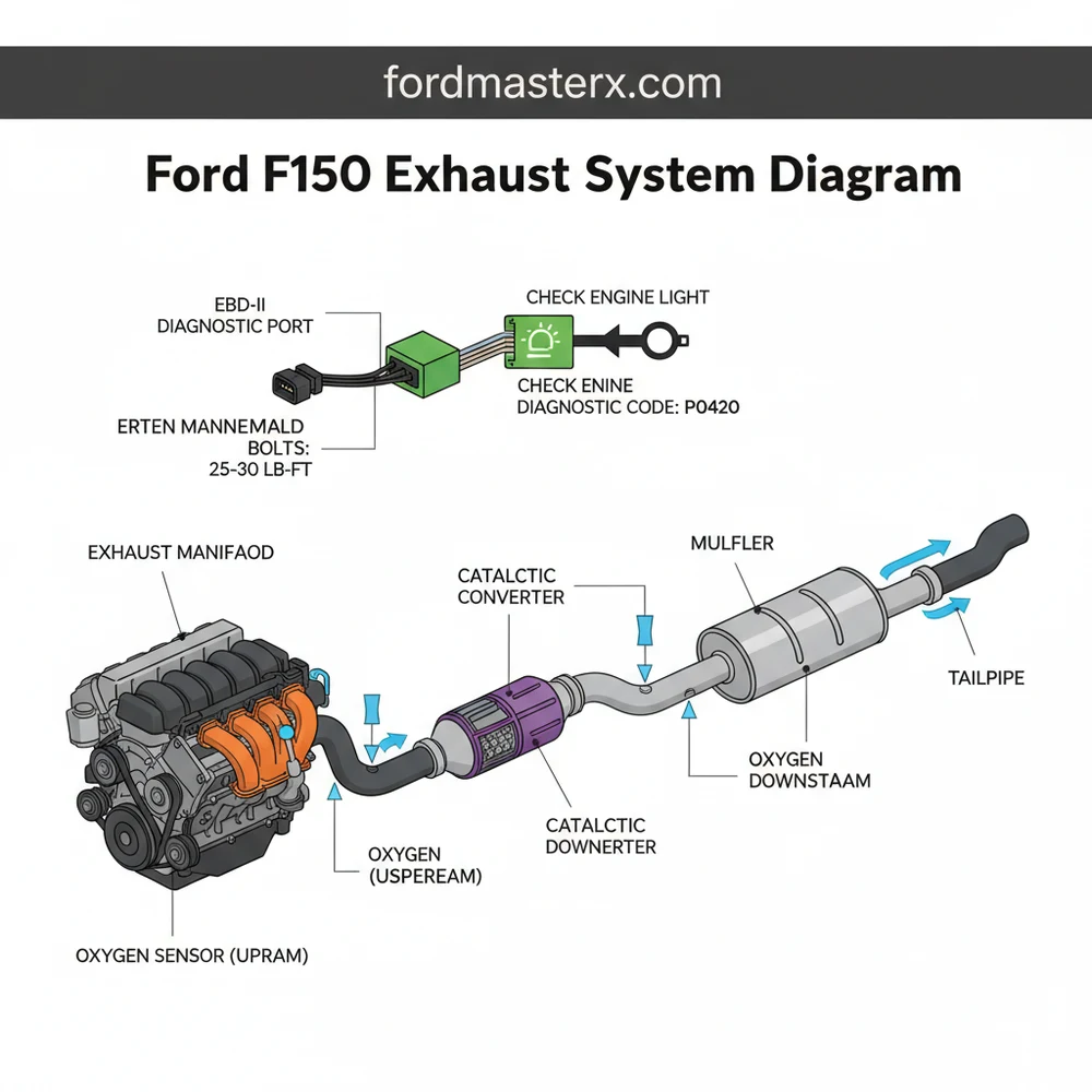
A Ford F150 exhaust system diagram illustrates the assembly of the manifold, Y-pipe, catalytic converter, muffler, and tailpipe. It highlights critical sensor locations that send data to the ECU. Using this visual guide helps you locate leaks and correctly reinstall components to maintain optimal engine performance and backpressure.
📌 Key Takeaways
- Accurately identify all components from the manifold to the tailpipe
- Locate upstream and downstream oxygen sensors for emission testing
- Understand the importance of maintaining correct backpressure for the ECU
- Identify rubber hanger locations to prevent exhaust rattles and vibrations
- Use the diagram to troubleshoot leaks that trigger the check engine light
For any truck owner, understanding the mechanical blueprint of their vehicle is the first step toward successful maintenance and performance tuning. When you are looking for a ford f150 exhaust system diagram, you are likely either troubleshooting a persistent rattle, dealing with a drop in fuel economy, or planning a custom upgrade. Having the correct diagram is essential because Ford F150 configurations vary significantly based on engine size, wheelbase, and trim level. This article provides a comprehensive guide to identifying every component from the manifold to the tailpipe, ensuring you have the technical clarity needed to perform repairs with confidence. You will learn how to identify sensor locations, understand the role of the emissions control system, and interpret the structural layout of the piping.
Understanding the Ford F150 Exhaust System Layout
The exhaust system of a Ford F150 is a sophisticated assembly designed to channel combustion gases away from the engine, reduce noise, and minimize harmful emissions. A standard ford f150 exhaust system diagram visually breaks down these components into a linear path. The process begins at the cylinder head, where the exhaust manifolds collect gases. In V6 and V8 models, there are two manifolds that merge into a Y-pipe. This section is critical because it houses the initial oxygen sensors that communicate directly with the ECU (Engine Control Unit) to manage fuel-to-air ratios.
As the gases move downstream, they enter the catalytic converters. These are the most valuable and technically complex parts of the system, responsible for converting carbon monoxide and hydrocarbons into less harmful substances. Most modern F150 diagrams will show a “dual-in, single-out” or “dual-in, dual-out” configuration depending on whether the truck has a single or dual exhaust setup. Behind the converters, you will find the resonator—a small chamber that cancels out high-frequency “droning” sounds—followed by the muffler, which provides the primary sound dampening. Finally, the tailpipe exits the system, usually behind the rear passenger wheel or straight out the back.
The Ford F150 exhaust system is modular. Components like the muffler and resonator are often connected via slip-fit joints or flanges, making it possible to replace sections rather than the entire assembly.
graph LR
    A[Exhaust Manifolds] --> B[Upstream O2 Sensors]
    B --> C[Y-Pipe / Collectors]
    C --> D[Catalytic Converters]
    D --> E[Downstream O2 Sensors]
    E --> F[Resonator]
    F --> G[Muffler]
    G --> H[Tailpipe & Tip]
    style D fill:#f96,stroke:#333,stroke-width:2px
    style A fill:#69f,stroke:#333,stroke-width:2px
Step-by-Step Guide to Reading and Using the Diagram
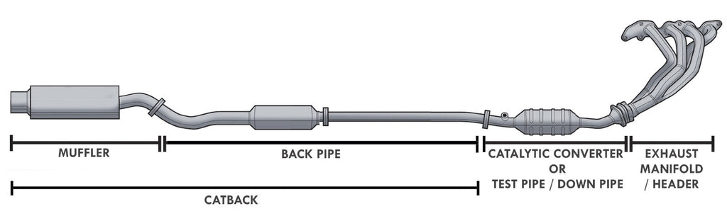
Interpreting a ford f150 exhaust system diagram requires a systematic approach. Whether you are replacing a rusted-out muffler or installing a high-performance cat-back system, follow these steps to ensure accuracy and safety.
- ✓ Identify Your Engine and Wheelbase: Before looking at a diagram, know if you have the 3.5L EcoBoost, 5.0L Coyote, or the 2.7L V6. The pipe lengths differ between the Regular Cab, SuperCab, and SuperCrew models.
- ✓ Locate the Oxygen Sensors: The diagram will show “Upstream” sensors (before the converter) and “Downstream” sensors (after). These are vital for the OBD-II system to monitor engine health.
- ✓ Note the Hanger Points: Exhaust systems are heavy. The diagram will indicate where rubber isolators and metal hangers support the weight of the pipes to prevent stress on the manifold.
- ✓ Check Flange and Bolt Locations: Look for the connection points between the Y-pipe and the catalytic converter. These often require specific torque specs during reassembly.
- ✓ Verify Gasket Placement: Every joint in the diagram typically requires a gasket or a specialized seal to prevent leaks that can trigger a check engine light.
Tools and Preparations
To work on your exhaust based on the diagram, you will need a deep socket set (specifically 13mm, 15mm, and 18mm), a can of penetrating oil (PB Blaster or WD-40), an O2 sensor wrench, and a torque wrench. Because exhaust bolts are subject to extreme heat cycles, they often seize. Spraying all bolts shown on your diagram 24 hours before starting the job is a critical best practice.
Never work on the exhaust system immediately after driving. Temperatures can exceed 1,000 degrees Fahrenheit near the manifold. Allow at least two hours for the system to cool completely.
Interpreting Sensor Data and the ECU
The exhaust system does more than just move air; it acts as a data center for the vehicle. The upstream sensors measure the raw exhaust to tell the ECU if the engine is running “lean” or “rich.” If you see a fault in your ford f150 exhaust system diagram near the sensors, it might be related to a timing chain issue or a vacuum leak affecting combustion, rather than the exhaust pipe itself. Proper interpretation involves looking at the system as part of a larger mechanical loop.
Common Issues and Troubleshooting with the Diagram

F150 owners frequently face specific exhaust-related challenges. Using your diagram to pinpoint the source of a problem can save hundreds in diagnostic fees.
Check Engine Lights and Diagnostic Codes: If your dashboard displays a check engine light, use an OBD-II scanner to pull the diagnostic code. Codes like P0420 or P0430 usually point to “Catalyst System Efficiency Below Threshold.” By referencing the ford f150 exhaust system diagram, you can locate the specific catalytic converter (Bank 1 or Bank 2) that needs inspection.
Exhaust Leaks and Ticking Sounds: A common issue on F150s is warped exhaust manifolds or broken manifold bolts. This often sounds like a rhythmic ticking that disappears as the engine warms up and the metal expands. Your diagram will show the bolt pattern for the manifold, which is essential for applying the correct torque spec during repair to prevent future warping.
Rattles and Vibrations: If you hear a metallic rattle, check the heat shields shown on the diagram. These thin aluminum sheets are bolted to the body or the pipes. Over time, the mounting holes can corrode, causing the shield to vibrate against the exhaust.
If you are experiencing a loss of power and a sulfur smell, your catalytic converter may be clogged. Use the diagram to locate the flange before the converter; unbolting it slightly to “breathe” can confirm if the blockage is in the converter or further back in the muffler.
Maintenance Tips and Best Practices
To keep your Ford F150 exhaust system in top condition, regular inspections are necessary. While the exhaust is a “passive” system, its health is dictated by the “active” systems of the engine.
Thermal Management and Fluid Leaks: Keep an eye on your coolant flow. If your engine is running hot due to a cooling system failure, the excess heat can prematurely degrade the internal ceramics of the catalytic converter. Similarly, ensure your accessory belt is in good condition; a failing water pump driven by that belt can lead to overheating that stresses every component in your exhaust diagram.
Material Choices: When replacing parts found on your diagram, consider the environment. If you live in the “salt belt,” look for T304 stainless steel components. While aluminized steel is cheaper, it will rust through significantly faster in snowy climates.
Torque Specifications: One of the biggest mistakes DIYers make is over-tightening exhaust clamps or under-tightening manifold bolts. Always refer to a service manual for the exact torque spec. For the Ford F150, manifold bolts usually require a specific sequence to ensure an even seal against the cylinder head.
Quality Components: When a diagnostic code points to a failed sensor, avoid “universal” O2 sensors. Stick to OEM (Motorcraft) or high-quality equivalents. The ECU on the F150 is sensitive to the resistance levels of these sensors, and cheap replacements often trigger a new check engine light immediately after installation.
In conclusion, a ford f150 exhaust system diagram is more than just a map of pipes; it is a vital tool for maintaining the efficiency, sound, and legality of your truck. By understanding how the manifold, sensors, converters, and mufflers work together, you can troubleshoot OBD-II codes, perform your own repairs, and ensure your vehicle remains on the road for years to come. Whether you are dealing with a minor rattle or a major manifold project, always prioritize safety, use the correct tools, and respect the complex engineering that goes into your Ford’s exhaust path.
Frequently Asked Questions
Where is the oxygen sensor located?
Oxygen sensors are located upstream and downstream of the catalytic converter. The Ford F150 exhaust system diagram shows these sensors mounted directly into the piping. They monitor gas levels and send signals to the ECU, which can trigger a check engine light if the air-fuel mixture or catalyst efficiency is off.
What does the exhaust diagram show?
The Ford F150 exhaust system diagram shows the complete routing of combustion gases from the engine block to the rear bumper. It identifies the manifold, flanges, resonators, mufflers, and the specific placement of O2 sensors. This visual aid is essential for identifying cracked pipes or failed gaskets during a repair.
How many sensor connections does it have?
Most Ford F150 exhaust systems utilize two or four oxygen sensors depending on the engine configuration. These sensors use multi-wire weather-pack connectors to interface with the OBD-II system. The diagram highlights these connection points, ensuring you don’t cross-wire sensors or leave any unplugged during a full system replacement.
What are the symptoms of a bad exhaust?
A failing system often produces loud roaring noises, localized hissing from leaks, or a distinct smell of raw fuel. You may notice a decrease in fuel economy or a check engine light on your dashboard. Using an OBD-II scanner can reveal a specific diagnostic code like P0420, indicating catalytic converter issues.
Can I replace this myself?
Replacing the exhaust system on a Ford F150 is a common DIY task for those comfortable with hand tools. While the components are heavy, the system is mostly bolt-on. Ensure you have high-quality jack stands for safety and refer to the diagram to ensure every gasket is properly seated.
What tools do I need for this task?
To work on the exhaust, you will need a socket set, a torque wrench to meet every specific torque spec, and penetrating oil like PB Blaster for rusted bolts. An OBD-II scanner is also helpful for clearing any stored diagnostic code after the installation of new sensors or converters.


