Ford F150 Coolant Hose Diagram: Complete Routing Guide
A 2013 Ford F150 coolant hose diagram maps the flow between the radiator, water pump, and engine block. It details the complex topology of the upper and lower radiator hoses, the heater core loop, and the reservoir connections, enabling owners to pinpoint leaks or identify failing quick-connect fittings quickly.
📌 Key Takeaways
- Provides a visual map of the engine’s thermal management topology
- The T-connector and degas bottle hoses are critical leak points to identify
- Always ensure the engine is cold before inspecting or disconnecting hoses
- Apply silicone lubricant to O-rings on quick-connect fittings for a better seal
- Use this diagram when diagnosing overheating or mysterious coolant loss
Maintaining the cooling system of a high-performance truck is a critical task for any vehicle owner, and having access to an accurate 2013 ford f150 coolant hose diagram is the foundation for successful maintenance. Whether you are dealing with a mysterious puddle in your driveway or an overheating engine on the highway, understanding how coolant circulates through your engine is essential. This guide provides a comprehensive breakdown of the hose network, identifying key components and flow paths. By the end of this article, you will be able to interpret the complex topology of your Ford’s cooling system, allowing you to perform repairs with the confidence of a professional technician.
Understanding the Cooling System Topology and Layout
The cooling system in a 2013 Ford F150 functions much like a sophisticated data network. To understand the 2013 ford f150 coolant hose diagram, it is helpful to view the engine as a central server and the hoses as the cabling that maintains system stability. The system topology is designed to distribute thermal loads across various subnets, such as the radiator, the heater core, and the transmission oil cooler. Each hose has a specific destination, much like an IP address, ensuring that fluid reaches the exact component requiring temperature regulation.
In this layout, the radiator acts as the primary gateway, managing the interface between the internal engine heat and the external environment. The thermostat serves as a switch, directing flow based on real-time temperature data. Smaller lines, such as the degas bottle return hoses, act as access points for air to escape the system, preventing air pockets that could lead to localized overheating. Depending on whether your F150 is equipped with the 3.5L EcoBoost, the 5.0L V8, or the 6.2L engine, the specific routing may vary slightly, but the fundamental logic of the network remains consistent across the platform.
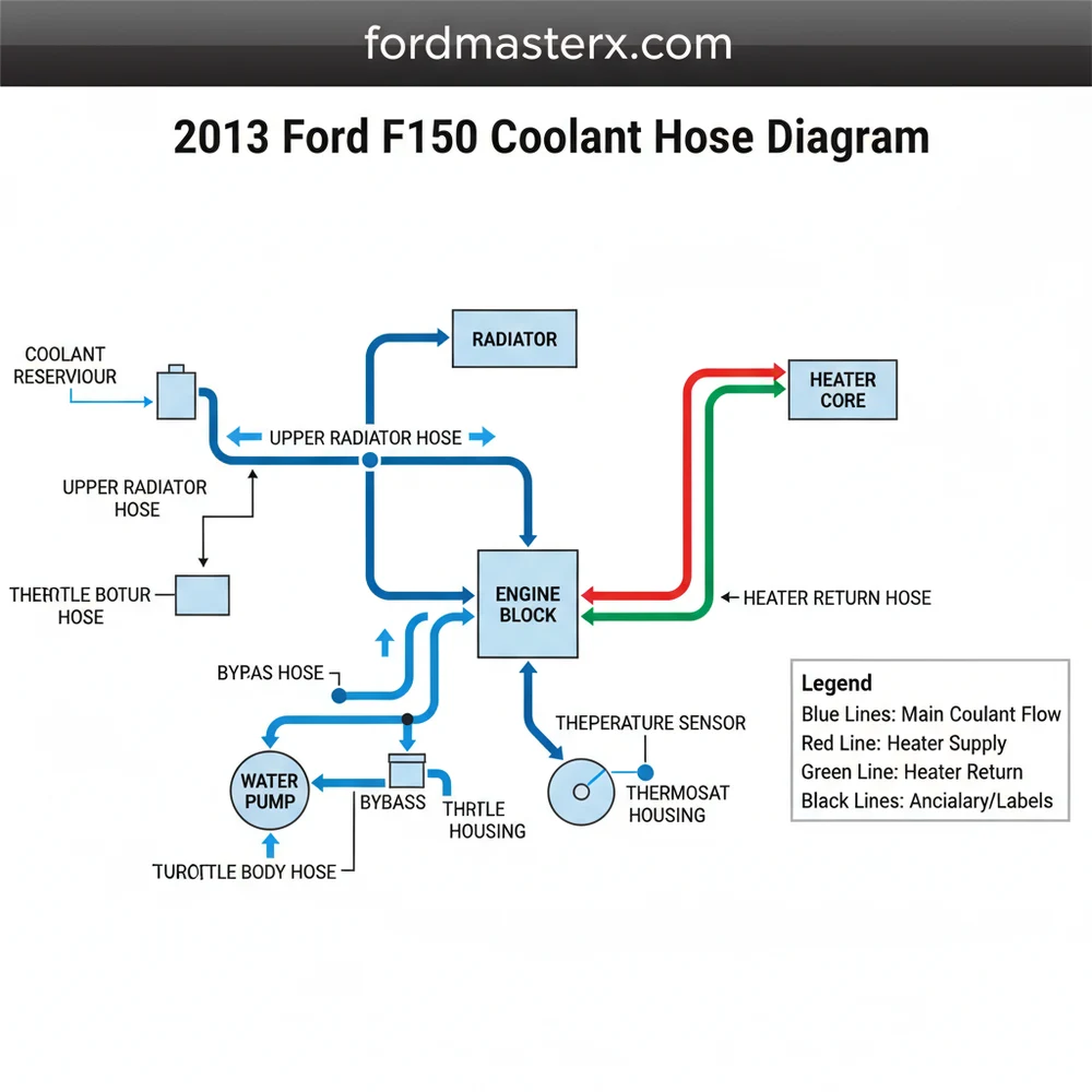
A visual representation of the coolant flow paths including the Upper Radiator Hose, Lower Radiator Hose, T-Connector Switch, Heater Core Subnet, and Degas Access Point.
The diagram typically utilizes a color-coding system to differentiate between high-pressure supply lines and low-pressure return lines. The primary upper radiator hose is the main “data trunk” for hot coolant leaving the engine, while the lower radiator hose serves as the return path for cooled fluid. Understanding the “DNS” (Designated Node System) of these parts—knowing which hose connects the water pump to the oil cooler versus the heater core—prevents costly installation errors.
The 2013 model year F150 often utilizes quick-connect fittings on several hoses. These require specialized tools or specific finger pressure to release, and the O-rings inside these connectors are a frequent point of failure in the system topology.
Step-by-Step Guide to Interpreting the Diagram and Replacing Hoses

Reading a 2013 ford f150 coolant hose diagram requires a systematic approach. Before you begin any physical work, you must map out the system to ensure you have the correct “IP address” for each part you intend to service. Follow these steps to interpret the diagram and execute a replacement safely.
- ✓ Step 1: Identify the Main Gateway – Locate the radiator in your engine bay and find the upper and lower hose connections. The upper hose is usually found on the driver’s side and carries the hottest fluid.
- ✓ Step 2: Trace the Switch Node – Follow the upper hose to the engine block. In many 2013 models, this leads to a T-connector or thermostat housing. This is a critical switch point in the system’s topology.
- ✓ Step 3: Map the Heater Subnet – Locate the two smaller hoses passing through the firewall. These are the heater core hoses. One is the supply (inlet) and one is the return (outlet).
- ✓ Step 4: Verify the Access Point – Identify the degas bottle (coolant reservoir). Trace the small-diameter overflow hoses that act as the system’s pressure relief and air bleed access points.
- ✓ Step 5: Inspect DHCP (Dynamic Hydraulic Circulation Process) – Check the water pump area, which acts as the system’s DHCP server, dynamically pushing fluid through the various network paths based on engine RPM.
- ✓ Step 6: Prepare the Infrastructure – Before removing any hose, ensure the engine is completely cold. Place a drain pan under the radiator petcock to catch the old coolant.
- ✓ Step 7: Disconnect and Install – Use a constant-tension clamp tool to slide the clamps back. For quick-connects, ensure the locking clip is fully disengaged before pulling.
- ✓ Step 8: System Reboot – Refill the system with the manufacturer-specified coolant and perform a “burping” procedure to remove air pockets, ensuring the new topology is fully operational.
Never attempt to open the degas bottle or remove a hose while the engine is hot. The cooling system is highly pressurized, and opening an access point under heat can result in severe steam burns.
To perform these tasks, you will need a basic set of tools: a set of pliers (specifically constant-tension hose clamp pliers), a screwdriver set, a drain pan, and fresh Motorcraft-approved coolant. If your truck features the EcoBoost engine, pay special attention to the turbocharger coolant lines, which represent a secondary subnet of hoses that require precision handling due to their proximity to high-heat exhaust components.
Common Issues and Troubleshooting the Hose Network

Even with a perfect 2013 ford f150 coolant hose diagram, issues can arise due to the age and mileage of the vehicle. One of the most frequent problems is “packet loss” in the form of small leaks at the T-connector. This component, which acts as a central switch between the radiator, water pump, and degas bottle, is notorious for O-ring failure. When this occurs, you may notice a slow drop in coolant levels without a visible puddle, as the fluid often evaporates on the hot engine block.
Another common issue is the degradation of the internal lining of the hoses. Over time, the “topology” of the hose can collapse internally, restricting flow. This is essentially a “bottleneck” in your network. If your truck is running hot but the radiator is cold, the “gateway” (thermostat) may be stuck, or the lower hose may be collapsing under the vacuum pressure of the water pump. Use your diagram to identify these specific nodes and check for signs of soft spots, bulging, or “crusty” residue at connection points, which indicates a slow-seeping leak.
Tips and Best Practices for Cooling System Maintenance
To ensure the longevity of your cooling network, follow these pro tips that go beyond the basic 2013 ford f150 coolant hose diagram. Regular maintenance prevents the “system downtime” associated with a blown hose or an overheated engine.
When replacing any hose, always replace the plastic T-connector with an aluminum aftermarket version if available. This upgrades the physical layer of your system’s topology and eliminates the most common failure point on the 2013 F150.
First, always use the correct coolant type. The 2013 F150 typically requires Orange-colored antifreeze (or the newer Yellow backward-compatible version). Mixing different types of coolant can cause a chemical reaction that creates “sludge,” essentially clogging the “subnets” of your heater core and radiator. Think of this as malware for your cooling system.
Second, consider a vacuum-fill tool when refilling the system. This ensures that every “subnet” and “node” is filled with fluid and completely free of air. Traditional “burping” can sometimes leave air trapped in the heater core, leading to poor cabin heat and erratic temperature readings. Finally, if you are replacing one major hose, it is often cost-effective to replace the others in that specific branch of the topology. If the upper radiator hose has reached its end of life, the lower hose and heater lines are likely not far behind. Investing in high-quality EPDM rubber hoses or silicone upgrades will provide a more robust infrastructure for your truck’s cooling needs.
By utilizing a detailed 2013 ford f150 coolant hose diagram and treating the system as a structured network, you can ensure your truck remains cool under pressure. Understanding the relationship between the gateway radiator, the switch-like thermostat, and the various hose subnets allows for precise troubleshooting and long-lasting repairs. Regular inspection of these components is the best way to prevent unexpected failures and keep your F150 performing at its peak for years to come.
Frequently Asked Questions
Where is the main coolant hose located?
The main upper radiator hose is located at the top of the engine bay, connecting the radiator to the thermostat housing. The lower hose connects the bottom of the radiator to the water pump, which serves as the primary gateway for coolant entering the engine block.
What does this coolant hose diagram show?
The diagram illustrates the routing of all primary and secondary hoses. It acts like a network map, showing how coolant moves through various subnets like the heater core and oil cooler, ensuring every part of the engine remains within its specified operating temperature range.
How many connections does the T-connector have?
The common T-connector on the 2013 F150 typically has three main connections. It links the upper radiator hose, the engine block, and the degas bottle. Each connection point must be verified for integrity, as they are high-pressure nodes in the system topology.
What are the symptoms of a bad coolant hose?
Symptoms include visible leaking at connections, a sweet smell under the hood, or engine overheating. If the PCM identifies a temperature spike, it may log an error code similar to an IP address conflict in a digital network, signaling a breakdown in thermal regulation.
Can I replace the coolant hoses myself?
Yes, coolant hose replacement is a manageable DIY task for most truck owners. By following the diagram, you can identify the specific subnet of hoses needing replacement. You will need basic hand tools and a catch pan to manage the fluid during the procedure.
What tools do I need for hose replacement?
You will need a set of pliers for spring clamps, a screwdriver for worm-gear clamps, and a specialized tool if your truck uses Ford’s quick-connect fittings. Having a diagnostic tool to check the cooling DNS (Digital Node Status) via the OBDII port is also helpful.