Ford F150 Brake Lines Diagram: Diagnosis & Fix Guide
The Ford F150 brake lines diagram illustrates the hydraulic paths from the master cylinder through the ABS module to each wheel caliper. It identifies primary and secondary lines, junction blocks, and flexible hoses. This guide helps owners pinpoint fluid leaks and navigate complex routing during line replacement or system bleeding.
📌 Key Takeaways
- Visualizing the hydraulic routing from the master cylinder to the wheels
- Identifying the ABS control module as a central junction point
- Ensuring all fittings are tightened to the correct torque spec
- Using the diagram to locate corrosion or physical damage in the lines
- Essential for bleeding the brakes or replacing rusted hard lines
Understanding the hydraulic architecture of your truck is the first step toward performing safe and effective maintenance. For many owners, a brake system ford f150 brake lines diagram is a vital resource that translates a complex web of steel and rubber into a manageable map. Whether you are dealing with the effects of road salt on the frame-mounted lines or simply upgrading your flexible hoses for better pedal feel, having a clear visual guide ensures that every connection is secure and every circuit is correctly routed. This article will break down the entire F-150 braking network, from the master cylinder to the individual wheel calipers, providing you with the technical knowledge needed for professional-grade DIY repairs.
The Ford F-150 utilizes a split-circuit hydraulic system. This means if one line fails, the other circuit provides enough pressure to bring the vehicle to a controlled stop, though with significantly increased pedal effort.
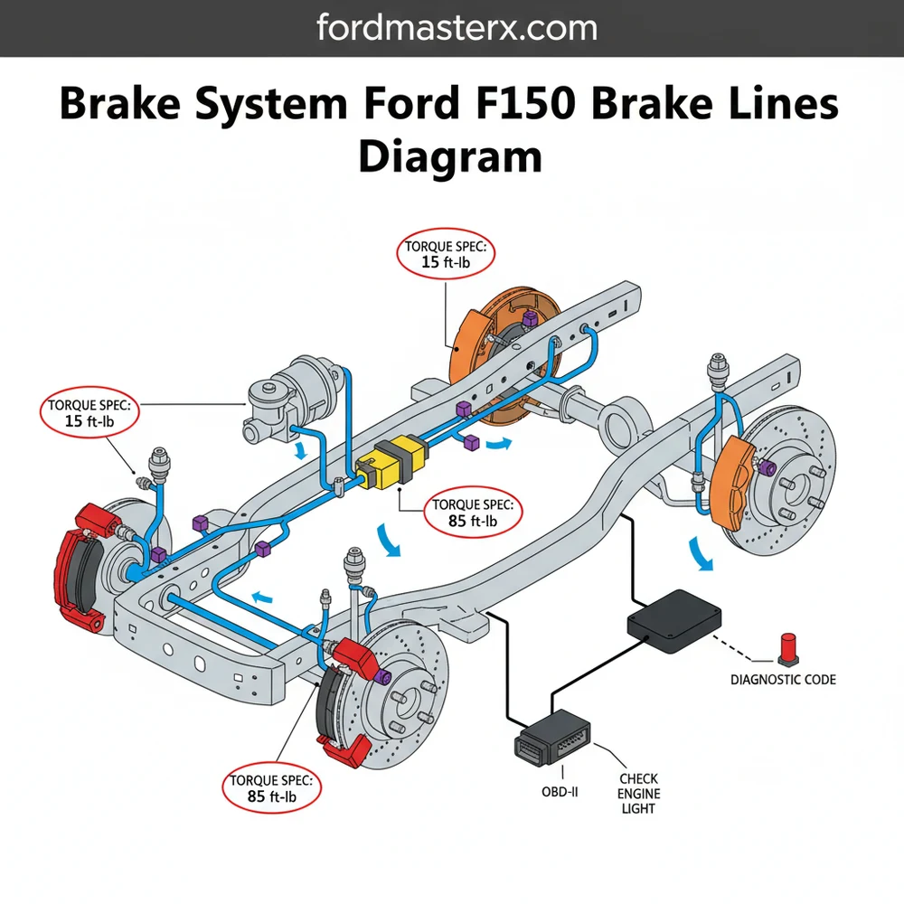
The primary brake system ford f150 brake lines diagram identifies several critical zones within the vehicle. At the top of the hierarchy is the master cylinder, mounted to the brake booster on the driver-side firewall. Two primary lines exit the master cylinder and travel a short distance to the Anti-lock Brake System (ABS) module, also known as the Hydraulic Control Unit (HCU). This unit is monitored by the ECU to modulate pressure during slip conditions.
From the ABS module, the system branches out. The front lines are the most direct; they run along the inner fender wells before transitioning from rigid steel tubing to flexible rubber hoses that connect to the calipers. The rear circuit is more extensive. A main supply line runs along the inner channel of the driver-side frame rail. This long run is often the most susceptible to corrosion. Near the rear axle, the line meets a flexible “drop hose” that allows for the vertical movement of the suspension. This hose connects to a “T” junction on the axle housing, splitting the fluid flow to the left and right rear wheels.
Diagrams typically use specific labeling to differentiate between the primary circuit (usually serving the front brakes) and the secondary circuit (usually serving the rear). It is important to note that while the layout remains consistent, the specific routing may shift slightly to avoid interference with other systems, such as the coolant flow pipes or the fuel vapor lines. High-quality diagrams will also specify the fitting sizes—typically M10 or M12 metric flares—and indicate the specific locations of the frame clips that prevent line vibration.
Figure 1: Conceptual Schematic of Ford F-150 Brake Line Routing (Split Circuit Configuration)
Reading and interpreting the diagram is the bridge between theory and practice. When you are under the chassis, the physical environment can be confusing; a diagram simplifies this by removing the clutter of the engine and transmission. To use the diagram effectively, follow this structured approach:
- ✓ Orient the Drawing: Always begin at the front of the vehicle. Locate the master cylinder in the diagram and find it under the hood to establish your perspective.
- ✓ Identify Line Materials: Distinguish between the “hard lines” (steel or NiCopp tubing) and the “soft lines” (rubber or braided stainless steel hoses). The diagram will show the transition points.
- ✓ Follow the Path: Trace the rear line from the ABS module back. Note where it passes through frame clips. If you are replacing a line, these clips must be reused or replaced to prevent the line from rubbing against the frame.
- ✓ Check for Intersections: Pay close attention to where lines cross. The diagram will show “over/under” routing to ensure the lines don’t come into contact with moving parts like the accessory belt or suspension arms.
- ✓ Verify Connections: Match the ports on your ABS module to the labels on the diagram. Swapping the front and rear ports will drastically change the braking bias and safety of the vehicle.
Before disconnecting any lines, use a digital camera to take photos of the routing. Use these photos in conjunction with the diagram to ensure the new lines are bent and installed in the exact factory orientation.
When performing the physical installation, safety is paramount. You will need flare nut wrenches (also known as line wrenches) to avoid rounding off the fittings. Standard open-end wrenches often fail on stubborn, rusted brake fittings. If you are fabricating your own lines, a high-quality double-flaring tool is required to create the specific inverted flare or bubble flare used in the Ford system. Always refer to the specific torque spec for your F-150 model when tightening fittings into the ABS module or calipers to ensure a leak-free seal without stripping the threads.
Common issues in the F-150 brake system often manifest as a spongy pedal or a localized leak. Because the brake lines are exposed to the elements, the sections along the frame rail are notorious for pinhole leaks caused by corrosion. A brake system ford f150 brake lines diagram helps you pinpoint these trouble spots by showing where the lines are most likely to trap moisture, such as behind plastic shields or near frame mounts.
If you encounter an illuminated ABS light on your dashboard, use an OBD-II scanner to pull the diagnostic code. Often, a code indicating low pressure in a specific circuit can be traced back to a compromised line or a failing flexible hose identified on the diagram. In some cases, a vacuum leak in the brake booster can even trigger a check engine light because it affects the engine’s intake manifold vacuum. Using the diagram to verify the integrity of the vacuum supply line to the booster is a critical troubleshooting step.
Never attempt to “patch” a brake line with a compression fitting meant for plumbing. Brake systems operate at pressures exceeding 1,000 PSI; only dedicated automotive flares and high-pressure fittings are safe for use.
To maintain the longevity of your brake system, consider the following best practices. First, if you live in a “salt belt” state, periodically rinse the frame rails where the brake lines are routed to remove corrosive debris. When it comes time for replacement, many professionals recommend using Nickel-Copper (NiCopp) tubing. This material is much more flexible than steel, making it easier to follow the complex bends shown in the diagram, and it is naturally resistant to rust.
While you are working on the brake system, it is an excellent time to inspect other nearby components. For instance, check the condition of the timing chain cover for oil leaks that might degrade rubber brake hoses, or ensure that your accessory belt is not fraying near the front brake lines. Keeping the engine bay clean and organized helps prevent secondary damage to your hydraulic system.
Finally, always perform a complete system bleed after opening any part of the hydraulic circuit. Start at the wheel furthest from the master cylinder and work toward the closest. By following the brake system ford f150 brake lines diagram and adhering to these maintenance protocols, you can ensure your truck remains a reliable and safe vehicle for years to come. Professional-grade results are possible for the DIYer who takes the time to understand the blueprint of their vehicle’s most critical safety system.
Step-by-Step Guide to Understanding the Ford F150 Brake Lines Diagram: Diagnosis & Fix Guide
Identify the master cylinder and ABS module on the diagram to understand the fluid source.
Locate the specific brake line segment that requires inspection or replacement along the chassis rail.
Understand how the lines are secured by mounting clips to prevent vibration and friction wear.
Connect new lines using flare nut wrenches, ensuring every fitting reaches the required torque spec.
Verify that the check engine light or brake warning light is cleared after the hydraulic repair.
Complete the process by bleeding the system and checking for any stored diagnostic code via OBD-II.
Frequently Asked Questions
Where is the master cylinder located?
The master cylinder is typically mounted on the driver-side firewall, attached to the brake booster. The diagram shows it as the starting point for hydraulic fluid, where pressure is generated. Locating it is crucial for checking fluid levels and identifying the origin of the primary brake lines.
What does the Ford F150 brake lines diagram show?
This schematic details the complete hydraulic path, including the master cylinder, ABS module, proportioning valve, and individual lines to each wheel. It serves as a blueprint for tracing fluid flow, helping mechanics identify where pressure might be lost due to a leak or blockage in the brake system.
How many brake lines does a Ford F150 have?
The truck generally features two main lines exiting the master cylinder, which branch out through the ABS module. From there, four individual lines travel to each corner of the vehicle. Technical diagrams also highlight the flexible rubber hoses located at each wheel to accommodate suspension travel and steering.
What are the symptoms of a bad brake line?
Common signs include a spongy brake pedal, visible fluid leaking under the chassis, and a low reservoir. If a leak causes significant pressure loss, the ECU may trigger a warning light on the dash, requiring a technician to scan for a specific diagnostic code to confirm the failure.
Can I replace Ford F150 brake lines myself?
Replacing brake lines is a feasible DIY task but requires precision. You must ensure every connection meets the manufacturer’s torque spec to prevent dangerous leaks. After installation, the system must be bled thoroughly to remove air, ensuring the brake pedal feels firm and responsive during vehicle operation.
What tools do I need for brake line replacement?
You will need flare nut wrenches to avoid stripping fittings, a tubing bender, and a flaring tool. Additionally, an OBD-II scanner might be necessary for newer models to cycle the ABS pump during the bleeding process, ensuring all air is purged from the internal valves and lines.