Ford F150 5.0 Engine Diagram: Quick Identification Guide
The Ford F150 5.0 engine diagram illustrates the layout of the V8 Windsor engine, including the intake manifold, distributor, and vacuum lines. Since these models feature OBD-II systems, this diagram is essential for locating sensors that trigger a diagnostic code or check engine light, ensuring accurate part replacement and maintenance.
📌 Key Takeaways
- Visualizes the layout of the 5.0L V8 Windsor engine components
- Helps identify sensor locations for OBD-II troubleshooting
- Ensure correct firing order by referencing distributor and plug wire routing
- Crucial for identifying vacuum line paths to prevent idle issues
- Best used during component replacement or electrical diagnosis
Navigating the engine bay of a classic pickup requires more than just a set of wrenches; it demands a clear roadmap. If you are working on a mid-nineties legend, having a high-quality 1996 ford f150 5.0 engine diagram is the difference between a successful weekend project and a frustrating afternoon of guesswork. As the final year for the ninth-generation “Old Body Style” (OBS) trucks, the 1996 model holds a unique place in automotive history, featuring the venerable 302 cubic-inch Windsor V8 paired with modern electronics. This guide provides a comprehensive breakdown of the engine’s architecture, helping you identify critical sensors, routing paths, and mechanical components to keep your truck running at peak performance.
The 1996 Ford F150 with the 5.0L V8 was a transition year. Unlike the 1995 models, the 1996 version is fully OBD-II compliant, meaning it uses an updated ECU and different sensor configurations than previous iterations of the Windsor engine.
Understanding the 1996 Ford 5.0L Engine Layout
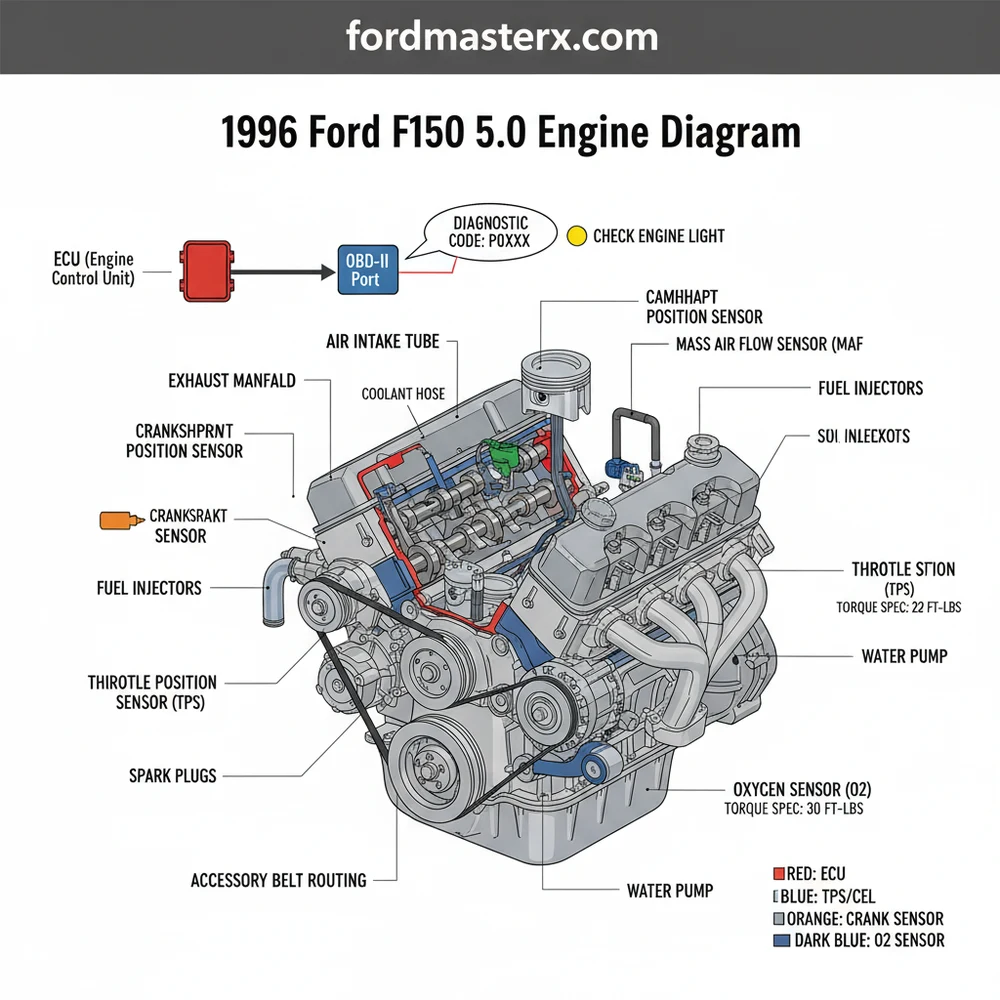
The 1996 Ford F150 5.0 engine diagram illustrates a sophisticated blend of traditional pushrod V8 design and first-generation digital engine management. At the top of the engine, you will notice the large, cast-aluminum upper intake manifold. This component dominates the visual space and is responsible for distributing air to the cylinders. Beneath this, the lower intake manifold houses the fuel injectors and connects directly to the cylinder heads. One of the most critical aspects of the 1996 diagram is the placement of the distributor at the front of the block, which is driven by the camshaft. Despite being an EFI (Electronic Fuel Injection) engine, the 5.0L still utilized a physical distributor for spark timing in 1996.
The diagram also highlights the accessory belt system, often referred to as the serpentine belt. In this specific year, the belt drives the alternator, power steering pump, air conditioning compressor, and the water pump. Understanding the routing of this belt is essential for any cooling system or charging system repairs. Furthermore, the 1996 model features a Mass Air Flow (MAF) sensor integrated into the air intake tube, a departure from the Speed Density systems used in many earlier F150s. This sensor communicates directly with the ECU to ensure the air-fuel ratio remains optimal.
Finally, the diagram identifies the cooling system path. The coolant flow starts at the water pump, moves through the engine block and cylinder heads, and exits through the thermostat housing located at the top front of the engine before returning to the radiator. Visualizing this flow is vital when diagnosing overheating issues or performing a system flush.
[DIAGRAM_PLACEHOLDER: A detailed 1996 Ford F150 5.0L Engine Diagram showing the Upper Intake Manifold, Serpentine Belt Routing, Distributor Location, Spark Plug Wire Firing Order (1-5-4-2-6-3-7-8), and OBD-II Sensor Locations including MAF, O2, and ECT sensors.]
How to Read and Apply the Engine Diagram

Interpreting an automotive diagram can be intimidating for beginners, but it is a systematic process. The 1996 ford f150 5.0 engine diagram serves as both a parts locator and a logic map for the truck’s mechanical systems. By following the steps below, you can use the diagram to perform maintenance and troubleshoot complex issues with confidence.
- ✓ Identify the Perspective: Most diagrams are drawn from the front of the vehicle looking back toward the firewall. Ensure you are orienting yourself correctly before loosening any bolts.
- ✓ Locate the Firing Order: For the 5.0L V8 (302 CID), the firing order is 1-5-4-2-6-3-7-8. The diagram will show the cylinder numbering (1-4 on the passenger side, 5-8 on the driver side).
- ✓ Trace the Vacuum Lines: These trucks are notorious for vacuum-related idle issues. Use the diagram to follow the lines from the intake manifold to the EGR valve, PCV valve, and brake booster.
- ✓ Map the Accessory Belt: Look for the tensioner pulley. The diagram will show which side of the belt (ribbed or smooth) touches each pulley.
- ✓ Find Electrical Grounds: Many ECU issues stem from poor grounding. The diagram identifies the main ground straps on the engine block and frame.
Always disconnect the negative battery terminal before performing electrical work or removing components like the alternator or starter. On the 1996 model, a short circuit can easily damage the sensitive OBD-II ECU.
When using the diagram for installation, such as replacing the timing chain or water pump, keep a set of labeled containers for your fasteners. The diagram can help you remember which bracket goes where, but organization on the workbench is equally important. For 1996 models, pay close attention to the specific torque spec listed for components like the intake manifold (typically 23-25 lb-ft) to avoid vacuum leaks or cracked castings. Having a calibrated torque wrench is as essential as having the diagram itself.
Common Issues and Diagnostic Troubleshooting

The 1996 Ford 5.0L is a workhorse, but age and heat cycles eventually lead to common failures. The 1996 ford f150 5.0 engine diagram is an invaluable tool when the check engine light illuminates. Because this is an OBD-II truck, you can use a standard scanner to pull a diagnostic code, which provides a starting point for your investigation.
One frequent issue is a “rough idle” or “stumbling under load.” This is often caused by a vacuum leak in the plastic lines that have become brittle over the last few decades. By cross-referencing the vacuum routing on your engine diagram, you can smoke-test or visually inspect the lines from the manifold to the canister purge solenoid. Another common culprit is the PIP (Profile Ignition Pickup) sensor inside the distributor. If your diagram shows you have spark at the coil but not at the plugs, the distributor internals are likely the cause.
If you receive a lean condition code (P0171 or P0174), use the diagram to locate the MAF sensor. Cleaning this sensor with specialized cleaner can often resolve the code without needing to replace expensive parts.
Additionally, keep an eye on the timing chain. While these engines are non-interference, a stretched timing chain can cause the valve timing to retard, leading to poor fuel economy and sluggish performance. If you hear a “slapping” sound from the front of the engine, consult the diagram to see the timing cover’s location and prepare for a front-end teardown. If the check engine light flashes, it indicates a severe misfire—use the firing order on the diagram to check your spark plug wire routing immediately.
Maintenance Tips and Best Practices
To keep your 1996 Ford F150 5.0 running for another 200,000 miles, proactive maintenance is mandatory. Using your engine diagram as a checklist, you should regularly inspect the accessory belt for cracks or fraying. A snapped belt on this engine means an immediate loss of power steering, alternator charging, and, most importantly, the water pump, which can lead to rapid overheating.
When it comes to the cooling system, ensure the coolant flow is unobstructed. Every 50,000 miles, perform a flush and replace the thermostat. When installing a new thermostat, ensure the “jiggle valve” or air bleed hole is at the 12 o’clock position to prevent air pockets. Consult your torque spec manual for the water pump bolts, as they pass through the timing cover and into the block; over-tightening can lead to snapped bolts and a much larger repair bill.
- ✓ Quality Gaskets: When removing the upper intake, always use high-quality Fel-Pro or OEM gaskets to ensure a perfect seal.
- ✓ Ground Cleaning: Periodically clean the battery terminals and the engine block ground mentioned in your diagram to prevent “phantom” electrical codes.
- ✓ Sensor Care: Only use high-quality oxygen (O2) sensors. The 1996 OBD-II system is sensitive to the voltage fluctuations of “no-name” sensors.
Finally, remember that the 5.0L Windsor is a flat-tappet or roller-cam engine depending on the specific block casting, but by 1996, they were almost universally roller blocks. This means they are less sensitive to zinc levels in the oil than older V8s, but high-quality conventional or synthetic blend 5W-30 oil remains the best choice for protecting the internal bearings and the timing chain. By combining the visual guidance of a 1996 ford f150 5.0 engine diagram with these best practices, you ensure your truck remains a reliable piece of American iron for years to come.
Step-by-Step Guide to Understanding the Ford F150 5.0 Engine Diagram: Quick Identification Guide
Identify the major components such as the upper intake manifold and air intake assembly.
Locate the distributor and spark plug wires to understand the firing order sequence.
Understand how the vacuum lines route between the intake and various emission sensors.
Connect an OBD-II scanner to the port under the dash to pull any diagnostic code.
Verify that all electrical connectors to the ECU and sensors are clean and tight.
Complete the repair by applying the correct torque spec to all replaced mounting bolts.
Frequently Asked Questions
Where is the ECU located?
The ECU is located behind the driver-side kick panel inside the cab or mounted through the firewall. It processes data from engine sensors to manage fuel injection and ignition timing. Accessing it is crucial when diagnosing electrical failures or if the truck will not communicate with an OBD-II scanner.
What does this engine diagram show?
This engine diagram shows the physical layout of the 5.0L V8 components, including belt routing, spark plug wire order, and vacuum hose connections. It serves as a visual map for mechanics to identify specific parts like the EGR valve, throttle body, and alternator during complex troubleshooting or routine maintenance.
How many wires does the O2 sensor have?
Most oxygen sensors on this model feature a four-wire connection, consisting of two heater wires, a signal wire, and a ground wire. These sensors send vital data to the ECU to adjust the air-fuel ratio. Proper wiring is essential to prevent a persistent check engine light and poor mileage.
What are the symptoms of a bad 5.0 ignition coil?
Symptoms include engine misfires, poor fuel economy, and stalling under load. A failing coil often triggers a specific diagnostic code related to ignition circuit failure. Using a diagram helps you locate the coil near the front of the engine for quick testing or replacement with basic hand tools.
Can I replace the intake manifold gasket myself?
Yes, replacing the intake gasket is a common DIY task, but it requires patience. You must follow a specific torque spec for the manifold bolts to prevent vacuum leaks. Having a diagram ensures you reconnect the numerous vacuum lines and electrical connectors to their correct positions during the reassembly process.
What tools do I need for engine work?
You will need a standard socket set (metric and SAE), a torque wrench for precise tightening, and an OBD-II scanner for reading codes. A set of screwdrivers and pliers is also necessary for removing hose clamps and electrical connectors found throughout the 5.0 engine bay during repairs.