Ford Econoline Side Door Latch Diagram: Component Guide
A Ford Econoline side door latch diagram illustrates the mechanical layout of the locking mechanism, including cables, rods, and latch assemblies. This visual guide helps identify each internal component and its connection to the exterior handle, ensuring you can troubleshoot alignment issues or replace a failing latch structure efficiently.
📌 Key Takeaways
- Visualizes the internal connection between handles and the latch assembly
- Identifies the latch structure, cables, and power lock actuator
- Safety requires disconnecting power locks before handling the system
- Regular lubrication of pivot points prevents rod and cable failure
- Use this diagram when the side door fails to stay shut or won’t unlock
Navigating the complexities of van maintenance often leads owners to the interior of their door panels, where a web of rods and cables governs access. Whether you are dealing with a door that refuses to open from the outside or a latch that won’t catch, a ford econoline side door latch diagram is the most critical tool in your arsenal. Having the correct schematic allows you to visualize the internal mechanics that are otherwise hidden behind steel skins and plastic trim. This article provides a comprehensive overview of the door latch system, teaching you how to identify every component, interpret the layout, and execute repairs with professional precision.
The Ford Econoline, or E-Series, utilizes two primary side door configurations: the 60/40 hinged swing-out doors and the sliding door system. While their outward operation differs, their internal latching logic remains remarkably similar, relying on a central remote control assembly connected to peripheral latches via high-tension cables or metal rods.
Understanding the Latch System Structure and Layout
The ford econoline side door latch diagram functions as a blueprint for the door’s skeletal system. At the heart of this configuration is the “Remote Control Assembly.” This is the central hub located behind the interior door handle. When you pull the handle, this assembly translates that motion into a pull force distributed to the upper and lower latch points. In the 60/40 door setup, the right-side (smaller) door usually contains the primary latch that secures into the body of the van, while the left-side (larger) door latches into the right door.
The schematic typically highlights three distinct zones. First is the “Actuation Zone,” which includes the interior and exterior handles and the power lock actuator. Second is the “Transmission Zone,” consisting of the rods or cables that span the height and width of the door. Third is the “Engagement Zone,” which houses the actual latch mechanisms—the metal “claws” that grab the strikers mounted on the van’s frame.
Most diagrams use a combination of solid lines to represent rigid rods and dashed or colored lines to represent flexible cables. Modern iterations of the Econoline frequently transitioned from rods to cables, which are more prone to stretching or end-connector failure. Understanding this layout is vital because a failure in the “Engagement Zone” often stems from a disconnect in the “Transmission Zone.” By studying the diagram, you can trace the path of mechanical energy from your hand at the handle down to the bottom sill of the door, identifying exactly where the system is losing its grip.
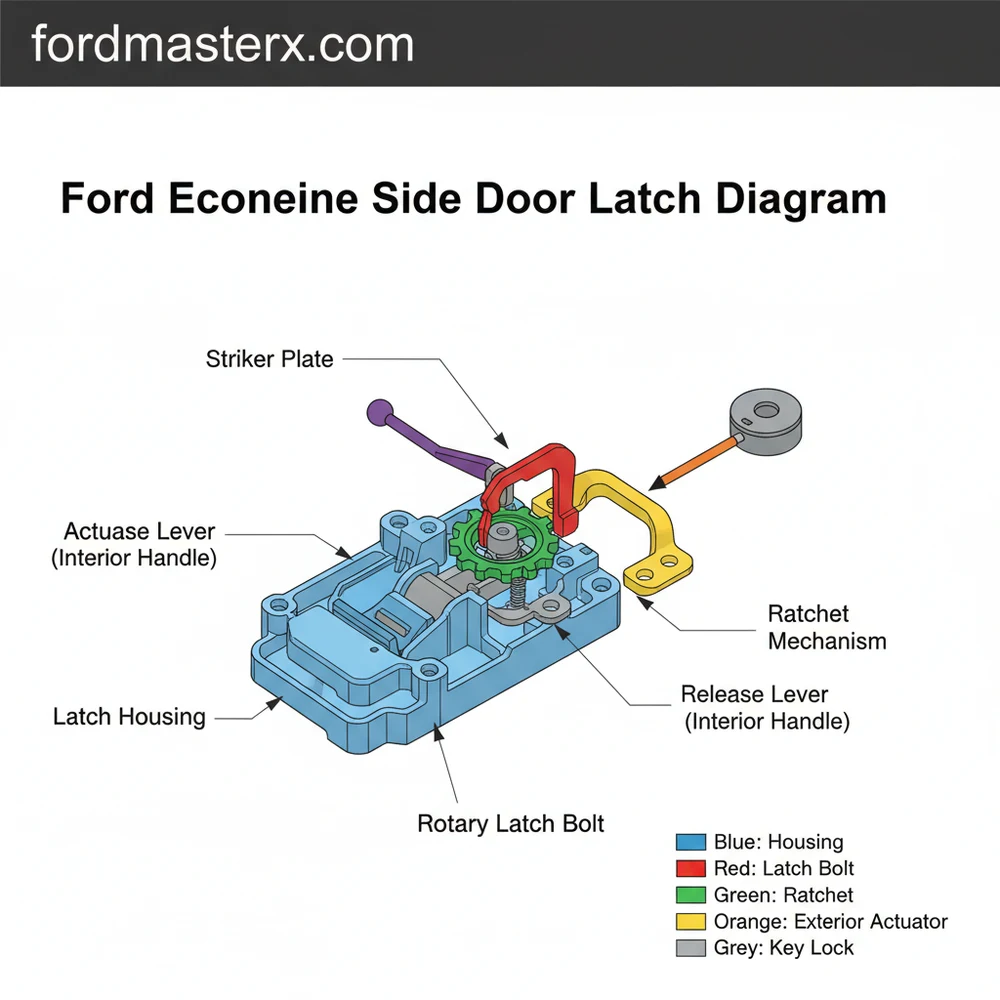
[DIAGRAM_PLACEHOLDER: FORD ECONOLINE SIDE DOOR LATCH SCHEMATIC]
Visualizing: 1. Exterior Handle 2. Internal Remote Hub 3. Upper Latch Cable 4. Lower Latch Cable 5. Power Lock Actuator 6. Door Striker Plates
Step-by-Step Guide to Interpreting and Applying the Diagram

To effectively use a ford econoline side door latch diagram for a repair, you must follow a systematic approach. Simply looking at the drawing is not enough; you must correlate the 2D blueprint with the 3D reality of the door cavity.
- ✓ Step 1: Preparation and Panel Removal – Before consulting the diagram, you must remove the interior door panel. Use a trim tool to pop the plastic clips and a Phillips head screwdriver for the armrest bolts. Be careful not to snap the brittle plastic clips, as these are not usually detailed in the mechanical latch diagram.
- ✓ Step 2: Orient the Schematic – Hold your diagram so it matches the orientation of the door. The “front” of the diagram should point toward the hinges. Identify the central remote control assembly first; this is your “North Star” for the rest of the repair.
- ✓ Step 3: Inspect the Cable Ends – Look at the diagram’s representation of cable terminations. In many Econoline models, the cables end in a “ferrule” or a plastic snap-in connector. Compare the diagram to your actual cables. If the cable is hanging loose but the diagram shows it attached to a lever, you have identified your primary failure point.
- ✓ Step 4: Test Component Movement – While looking at the configuration shown in the schematic, have an assistant pull the exterior handle. Watch the rods or cables. Do they move the full distance indicated by the layout? If a rod moves but the latch doesn’t click, the issue is internal to the latch mechanism itself.
- ✓ Step 5: Replace or Repair Connections – Use the diagram to ensure rods are bent in the correct direction and cables are routed through their designated guides. Misrouting a cable—even by an inch—can cause it to bind against the window glass or internal bracing.
- ✓ Step 6: Synchronizing the Latches – On swing-out doors, the upper and lower latches must release simultaneously. The diagram will show an adjustment screw or a threaded rod connector at the central hub. Use this to fine-tune the tension so both latches “pop” at the same moment.
Never attempt to slam the door shut if the latches are in the “closed” position while the door is open. Use a screwdriver to manually trip the latch to the “open” position before testing the door swing. Failure to do so can bend the striker or damage the latch internals.
Common Issues and Troubleshooting Techniques

The most frequent issue encountered with the Ford Econoline side door system is the “deteriorating cable end” syndrome. Over time, the plastic housing that holds the cable tension against the latch bracket cracks and falls away. When this happens, the cable simply slides through the bracket instead of pulling the lever. The ford econoline side door latch diagram helps here by showing you the exact shape the connector should have, allowing you to see what is missing.
Another common problem is a “frozen” lower latch. Because the lower latch is positioned near the road surface, it is constantly bombarded by moisture, salt, and debris. It may become seized, preventing the central remote from pulling the cable. If you pull the handle and feel significant resistance, do not force it. Consult the schematic to find the access point for the lower latch and apply a penetrating catalyst directly to the moving parts identified in the drawing.
Signs of a failing system include a handle that feels “loose” or “floppy,” a door that requires a secondary push to latch fully, or an electronic lock that cycles but doesn’t actually secure the door. If the power locks aren’t working, the diagram will help you locate the solenoid/actuator, which is usually a separate component clipped onto the main latch assembly.
Pro Tips and Maintenance Best Practices
To maximize the lifespan of your Ford Econoline’s door hardware, maintenance is key. One of the best pro-tips for these vans is to move away from the factory plastic cable ends. Many aftermarket manufacturers offer CNC-machined aluminum end-pieces. These permanent fixes replace the brittle plastic shown in your original blueprint and ensure the cable never slips again.
When lubricating your door system, avoid heavy greases that attract dust. Instead, use a high-quality dry silicone spray or a white lithium grease in an aerosol can with a straw. This allows you to reach the pivot points identified on your ford econoline side door latch diagram without gumming up the works.
Quality of components also matters. If you are replacing a full latch assembly, try to find OEM (Original Equipment Manufacturer) parts. While aftermarket options are cheaper, the tolerances on the striker engagement are very tight in the E-Series. A latch that is off by even two millimeters can cause persistent rattling or wind noise while driving.
Regularly check the “striker” plates on the van body. These are the metal loops the latches grab onto. If the plastic bushing on the striker is missing, the door will not sit flush, causing undue stress on the latch. Referring back to your ford econoline side door latch diagram will show you the relationship between the latch and the striker, reminding you that a repair often involves both sides of the door’s edge. By staying proactive and using the schematic as your guide, you can keep your Econoline’s side doors operating smoothly for years to come, ensuring the safety and security of your vehicle’s contents.
Frequently Asked Questions
Where is the door latch component located?
The side door latch is located inside the door shell, mounted directly to the trailing edge of the door frame. It is secured by three Torx bolts that are visible from the side profile of the door when it is in the open position.
What does this latch diagram show?
The diagram displays the complete mechanical configuration of the door. It maps out the layout of the release rods, the cable routing from the handles, the mounting points for the latch assembly, and the connection points for the power lock actuator within the door structure.
How many connections does the latch system have?
The standard system features three primary mechanical connections: the rod for the interior release handle, the cable or rod for the exterior handle, and the linkage for the lock cylinder. Additionally, power-equipped models include an electrical connector for the locking actuator.
What are the symptoms of a bad latch?
Common symptoms include a door that bounces back when closed, handles that feel loose or have no resistance, or a door that remains stuck shut. These issues often stem from a failed spring within the latch structure or a stretched cable in the system.
Can I replace this myself?
Yes, replacing the latch is a common DIY task. It requires removing the interior trim panel to access the internal system components. While the workspace is tight, following a diagram makes it simple to disconnect the rods and swap the unit with basic hand tools.
What tools do I need for this task?
You will typically need a set of Torx bits (specifically T-27 or T-30), a flat-head screwdriver for prying trim clips, and needle-nose pliers. These tools allow you to unfasten the latch from the frame and safely detach the rod clips without breaking them.


