Ford E350 Air Conditioning Diagram: Complete System Guide
A Ford E350 air conditioning diagram displays the refrigerant flow through the compressor, condenser, evaporator, and accumulator. It outlines the electrical configuration of sensors and switches, allowing you to identify how high-pressure and low-pressure lines interact within the overall system structure for effective cabin cooling and climate control.
📌 Key Takeaways
- Visualizes the refrigerant flow and electrical links within the HVAC system.
- The AC compressor and clutch assembly are the most critical parts to identify.
- Always follow safety precautions when handling high-pressure refrigerant lines.
- Use the diagram to locate electrical shorts in the AC clutch circuit.
- Essential for troubleshooting intermittent cooling or total system failure.
When your Ford E350’s cabin begins to feel more like a sauna than a sanctuary, understanding the inner workings of your HVAC system becomes a top priority. Whether you are driving a cargo van, a passenger wagon, or a cutaway chassis used for an RV conversion, a clear and accurate ford e350 air conditioning diagram is your most valuable asset. This blueprint provides a visual roadmap of how refrigerant moves through the various hardware components to remove heat from the interior. By studying the system’s layout, you will gain the knowledge necessary to identify faulty parts, locate leaks, and perform routine maintenance that ensures your vehicle stays cool during the hottest months.
Detailed Configuration and Component Overview
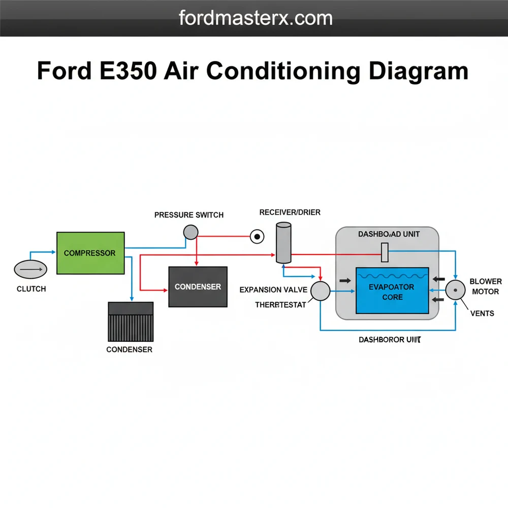
The core structure of a ford e350 air conditioning diagram typically revolves around a closed-loop system comprised of five primary components: the compressor, the condenser, the orifice tube (or expansion valve), the evaporator, and the accumulator. In the standard layout, the compressor serves as the heart of the system, mounted to the engine and driven by the serpentine belt. The diagram illustrates how the compressor pressurizes the refrigerant, sending it as a high-pressure gas to the condenser, which is located in front of the radiator to maximize airflow.
As you analyze the schematic, you will notice a distinct division between the “High Side” and the “Low Side.” The high-pressure lines are often depicted with smaller diameters or specific color-coding (usually red), while the low-pressure suction lines are larger and often coded blue. For E350 models equipped with rear auxiliary cooling, the configuration becomes more complex, featuring a series of long underbody lines that lead to a second evaporator core located in the rear of the cabin. This extended blueprint includes T-junctions and additional block valves that are critical for troubleshooting cooling imbalances between the front and back of the vehicle. Identifying the specific component locations on the chassis—such as the accumulator located near the firewall—is essential for accurate diagnosis.
The blueprint also highlights the importance of the accumulator, which is positioned on the low-pressure side. Its primary function in the ford e350 air conditioning diagram is to act as a reservoir for refrigerant and to filter out moisture through an internal desiccant. Because the E350 is a heavy-duty platform, the system capacity is significantly larger than a standard sedan, often requiring more than 30 ounces of R134a refrigerant for a front-only system and upwards of 60 ounces for dual-unit configurations. Understanding these measurements via the system overview prevents overcharging, which can be just as damaging to the compressor as a leak.
[DIAGRAM_PLACEHOLDER – Ford E350 AC System Schematic showing Compressor, Condenser, Evaporator, and Line Layout]
The Ford E350 often utilizes a CCOT (Cycling Clutch Orifice Tube) system. Unlike systems with an expansion valve that adjusts flow dynamically, the CCOT system uses a fixed-diameter tube and cycles the compressor on and off via a pressure switch to regulate the cabin temperature.
Step-by-Step Guide to Interpreting the Schematic
Reading a technical schematic can be daunting for the uninitiated, but following a systematic approach allows you to master the Ford E350 air conditioning layout. Use these steps to interpret the diagram and apply it to your vehicle’s physical hardware.
- Identify the Power Source: Start by locating the compressor on your diagram. This is the mechanical hub. Verify the electrical connection to the compressor clutch, as the diagram will show the wiring route from the AC relay and the high/low pressure switches.
- Trace the Refrigerant Flow: Follow the lines from the compressor discharge port to the condenser. On the diagram, this path represents the hottest part of the system. In the physical vehicle, ensure the condenser fins are not blocked by leaves or debris, which the layout shows as the first stage of heat dissipation.
- Locate the Metering Device: Find the orifice tube on the blueprint. In many Ford E350 models, the orifice tube is located inside the liquid line near the evaporator inlet (often where the line connects to the firewall). This small component is a frequent site for clogs and is a critical checkpoint on the schematic.
- Distinguish the Service Ports: Use the diagram to identify the high-side and low-side service ports. The high-side port is usually located on the line between the compressor and the orifice tube, while the low-side port is found on the accumulator. Never mix these up during testing, as they have different fitting sizes for safety.
- Map the Electrical Logic: The schematic isn’t just about pipes; it includes the high-pressure and low-pressure cutout switches. These are safety components that tell the compressor to stop if pressures are too high (preventing explosion) or too low (preventing compressor oil starvation). Locate these on the diagram to test for electrical continuity if your clutch won’t engage.
- Verify Auxiliary Connections: If your E350 is a passenger van or ambulance, look for the “T” branches on the diagram. These lead to the rear unit. Following these lines under the vehicle will help you find potential leak points in the long aluminum or rubber hoses that run the length of the frame.
To use the diagram effectively for a repair, you will need a set of manifold gauges, a vacuum pump, and basic hand tools like a fan clutch wrench or quick-disconnect line tools. Having the diagram open while you attach your gauges ensures you are reading the correct pressures for the corresponding part of the system cycle.
Air conditioning systems are under extremely high pressure. Never attempt to disconnect lines or replace components without first recovering the refrigerant using a professional recovery machine. Venting refrigerant into the atmosphere is illegal and environmentally hazardous.
Common Issues and Troubleshooting with the Diagram

When your system fails, the ford e350 air conditioning diagram acts as a diagnostic checklist. One of the most common issues is a “short cycling” compressor, where the clutch engages and disengages every few seconds. By referencing the schematic, you can locate the low-pressure switch; if the refrigerant level is low, this switch breaks the circuit to protect the compressor from running without oil.
Another frequent problem involves “Black Death,” a term used when the compressor internals break down and circulate metallic debris throughout the system. The layout helps you identify where this debris will likely collect—specifically the orifice tube and the condenser. If the diagram shows a blockage at the orifice tube, it is a clear sign that the system needs a deep flush and component replacement. Look for oily residue on any of the joints or hoses identified in the blueprint, as refrigerant carries oil; a greasy spot almost always indicates a leak point. If the air is only cold while the vehicle is moving, the diagram points you toward the condenser fan or airflow issues rather than a mechanical failure of the refrigerant cycle itself.
Best Practices and Maintenance Tips
To keep your Ford E350 AC system running efficiently for years, follow these maintenance guidelines based on the system’s intended design and structure.
Always replace the accumulator/drier whenever the system is opened to the atmosphere for more than a few minutes. This component contains a desiccant that absorbs moisture; once saturated by humidity, it can lead to internal corrosion and ice blockages that the diagram cannot fix.
- ✓ Use Correct Oil: Always use the specific PAG oil viscosity (usually PAG 46 or 100) as noted in the system specifications. The wrong oil can lead to premature compressor seizure.
- ✓ Clean the Condenser: Regularly spray the condenser fins with low-pressure water to remove salt, bugs, and road grime. This maintains the heat exchange efficiency shown in the blueprint.
- ✓ Belt Inspection: Inspect the serpentine belt for cracks or glazing. A slipping belt will prevent the compressor from reaching the necessary RPMs required to reach high-side pressures.
- ✓ Line Routing: When replacing lines, ensure they are routed exactly as shown in the ford e350 air conditioning diagram to avoid contact with hot exhaust components or moving engine pulleys.
- ✓ Vacuum Testing: Before recharging, always pull a vacuum for at least 30 minutes. This boils off moisture and confirms the system is airtight.
Investing in high-quality, OEM-specification components rather than generic “one-size-fits-all” kits is highly recommended for the E350. These vehicles often operate under heavy loads or carry many passengers, meaning the cooling system must be robust enough to handle high volumes of air. By maintaining the integrity of the original system configuration and using an accurate ford e350 air conditioning diagram for every repair, you avoid costly recurring failures and ensure a comfortable environment for every journey. Whether you are performing a simple recharge or a full compressor swap, the layout remains your primary guide to success.
Frequently Asked Questions
Where is the Ford E350 AC compressor located?
The AC compressor is typically located on the front engine block, driven by the serpentine belt. In the Ford E350 configuration, it is often found on the upper passenger side or lower driver side depending on the engine type, allowing for easy access to the pulley and electrical connector.
What does a Ford E350 air conditioning diagram show?
The diagram illustrates the complete layout of the HVAC system, including the refrigerant lines, the orifice tube, and the electrical structure. It helps identify how the PCM controls the compressor clutch based on input from the high-pressure and low-pressure cycling switches within the cooling system.
How many connections does the E350 AC compressor have?
Most Ford E350 compressors feature two main refrigerant line connections for suction and discharge and a two-pin electrical connector for the clutch coil. This configuration allows the vehicle’s computer to engage or disengage the cooling cycle based on pressure readings received from the system’s sensors.
What are the symptoms of a bad AC compressor?
Common symptoms include the air conditioner blowing warm air, loud grinding noises when the system is engaged, or a seized pulley that snaps the serpentine belt. If the compressor clutch fails to engage despite having power, it usually indicates an internal component failure or a faulty coil.
Can I replace the AC components myself?
While you can replace physical components like the compressor or accumulator, the refrigerant must be professionally recovered and recharged using specialized vacuum equipment. Handling pressurized R134a requires safety gear and adherence to environmental regulations to prevent harmful atmospheric leaks during the repair process.
What tools do I need for AC repair?
Essential tools include a manifold gauge set to monitor system pressure, a vacuum pump for moisture removal, and specialized quick-disconnect tools for the refrigerant lines. You will also need standard socket sets to remove mounting bolts and a torque wrench for proper reinstallation of the component.


