Ford Clutch Pedal Assembly Diagram: Complete Guide
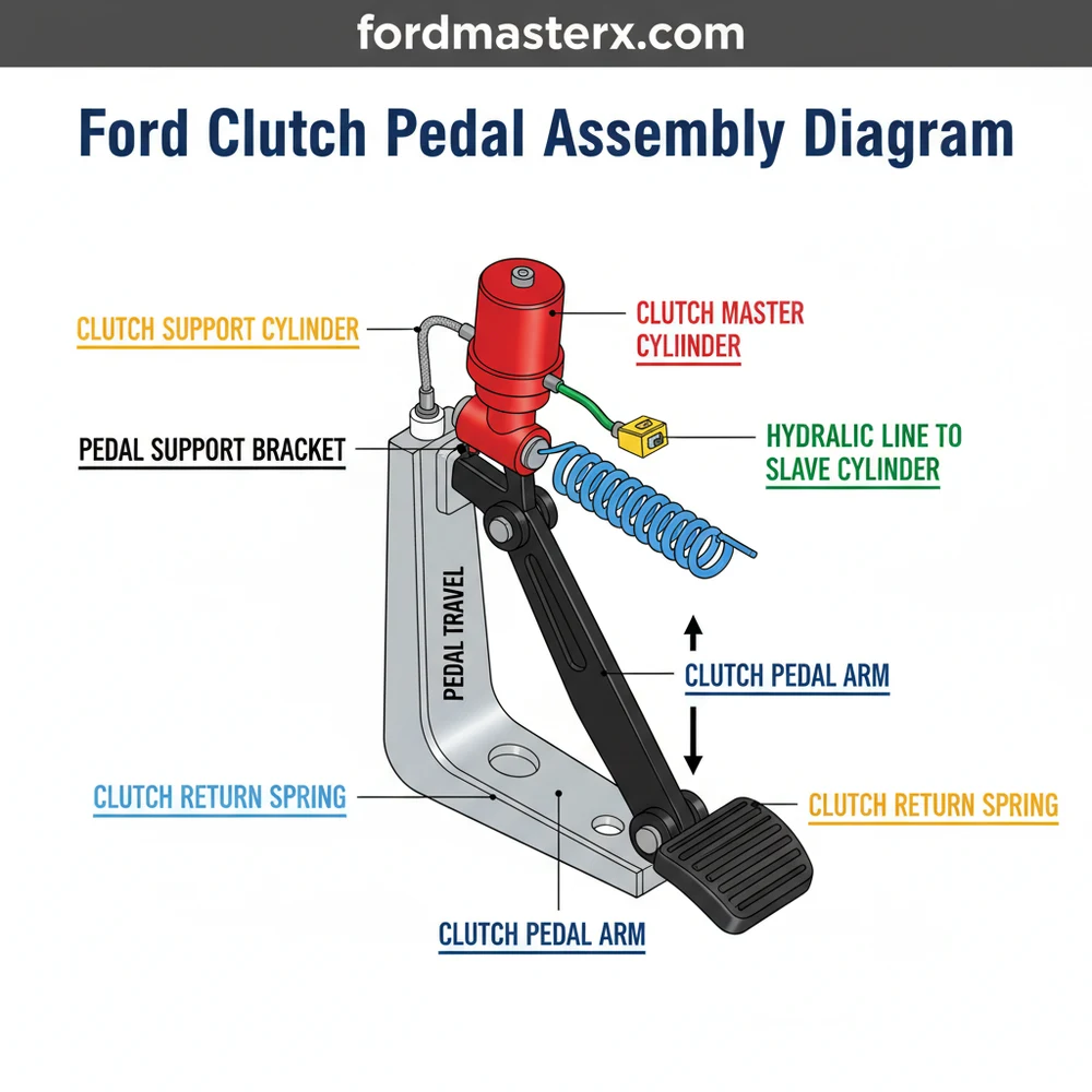
A Ford clutch pedal assembly diagram provides a visual layout of the mechanical system, including the pedal arm, return spring, bushings, and master cylinder linkage. This configuration is essential for identifying worn components or understanding the connection between the driver’s input and the hydraulic system to ensure smooth gear shifts.
📌 Key Takeaways
- Provides a visual map of the entire pedal system layout.
- The pivot bushings are the most important components to identify for wear.
- Always ensure the return spring is properly tensioned for safety.
- Use the diagram to check for alignment between the pedal and master cylinder.
- Consult this diagram when experiencing a soft pedal or grinding gears.
The clutch pedal assembly in a Ford vehicle is a critical mechanical and hydraulic link that allows the driver to disengage the transmission from the engine. Whether you are working on a classic Fox Body Mustang, a rugged OBS (Old Body Style) F-150, or a modern Focus, the fundamental architecture of the Ford clutch pedal assembly remains relatively consistent, though the materials have transitioned from heavy-duty steel to lightweight composites over the decades. For the DIY enthusiast, understanding a clutch pedal assembly diagram is the first step in diagnosing common issues such as “dead pedal” syndrome, grinding gears, or a vehicle that refuses to start. This guide provides a deep dive into the anatomy of these systems, offering the technical specifications and practical insights needed to master your next repair or restoration project.
Main Components and Features of the Ford Assembly
A standard Ford clutch pedal assembly is more than just a lever; it is a complex mounting bracket system housed under the dashboard, often shared with the brake pedal. When looking at a technical diagram, you will typically find the following primary components:
- The Pedal Arm: Usually constructed of stamped steel or high-density plastic. This is the main lever that provides the mechanical advantage required to compress the heavy pressure plate springs.
- The Pivot Shaft and Bushings: The pedal rotates on a steel shaft. In most Ford models, especially from the 1980s through the early 2000s, this shaft uses nylon or “oilite” bronze bushings. These are notorious for wearing thin, leading to a “sideways” wiggle in the pedal.
- Clutch Master Cylinder Pushrod: This rod connects the pedal arm to the hydraulic master cylinder. On many Ford trucks, the rod attaches via a plastic bushing that is a frequent point of failure.
- The Return/Assist Spring: Ford uses two types of springs: a heavy-duty assist spring (to make the pedal easier to push) and a return spring (to ensure the pedal returns to the top of its travel).
- Clutch Pedal Position (CPP) Switch: Also known as the neutral safety switch. This electrical component prevents the engine from cranking unless the pedal is fully depressed.
- Firewall Mounting Bracket: The heavy-duty frame that bolts to the firewall and supports both the clutch and brake pedals.
How to Read and Use the Diagram

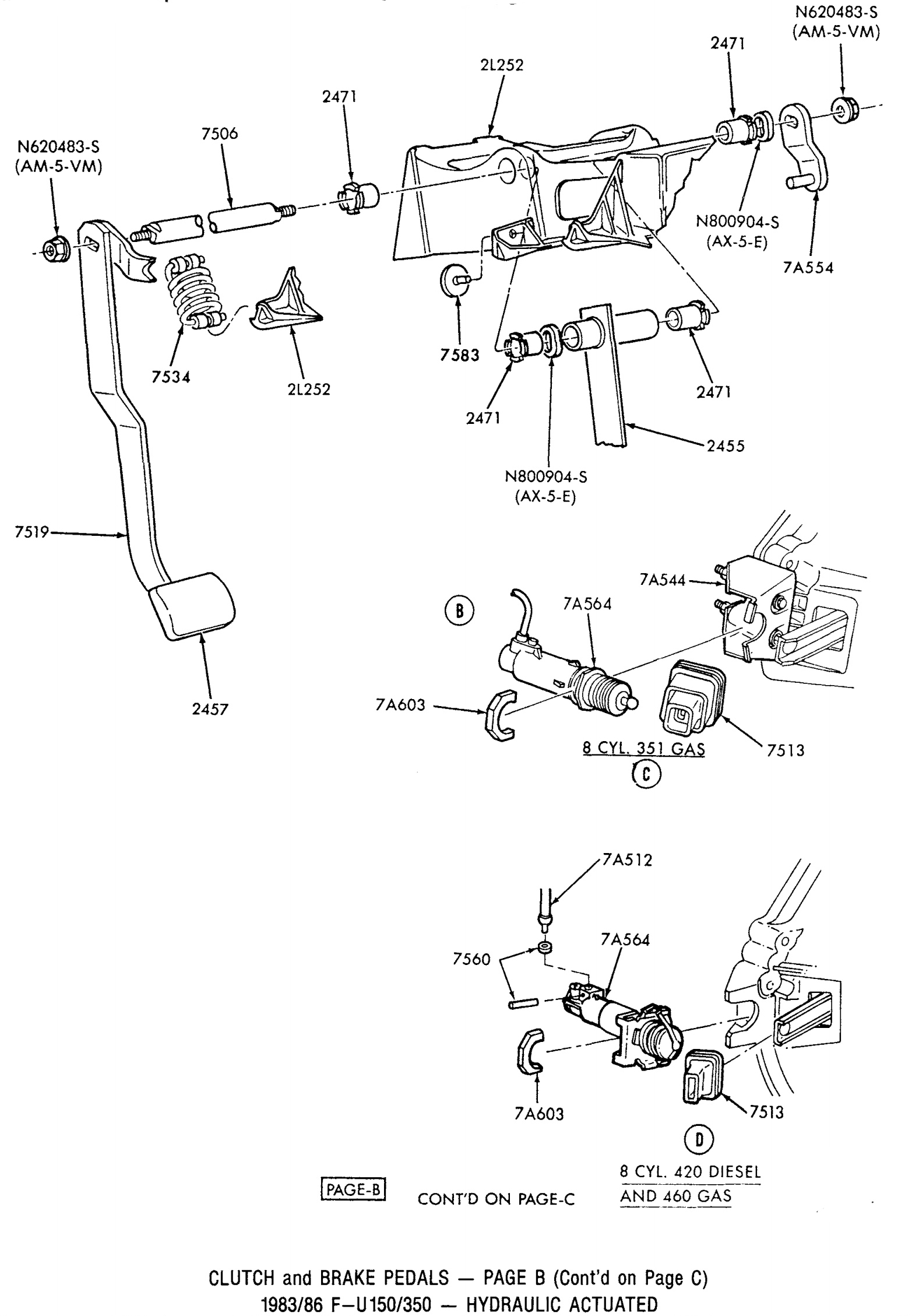
Reading a Ford factory service manual (FSM) or an aftermarket exploded view diagram requires an understanding of how parts are layered. Most Ford diagrams use an “exploded view” format where lines indicate how bolts pass through various components. Here is how to navigate them effectively:
First, identify the Orientation. Most diagrams show the assembly from the driver’s side perspective. Look for the firewall interface; this is where the assembly bolts through the cab and into the engine bay. On most Fords, you will see four main mounting studs that also secure the brake booster.
Second, follow the Linkage Path. Trace the line from the pedal pad up to the pivot point, and then look for the horizontal offset that connects to the master cylinder. In hydraulic systems, this is a direct pushrod. In older cable-operated Fords (like 1979–2004 Mustangs), the diagram will show a plastic “quadrant” at the top of the pedal where the cable hooks in.
Third, note the Fastener Schedule. Diagrams usually label bolts with specific sizes. In modern Ford assemblies, the mounting nuts are typically 13mm or 15mm. Pay close attention to “one-time use” clips, often labeled as “C-clips” or “E-clips,” which retain the pivot pins. If the diagram shows a jagged line through a component, it indicates an assembly that should be replaced as a single unit rather than serviced individually.
Technical Details and Specifications
For DIYers performing a repair or a manual swap, specific measurements and electrical data are vital. While these can vary by year, certain “Ford Standards” apply across many platforms:
The CPP Switch Wiring: If your vehicle won’t start, the Clutch Pedal Position switch is often the culprit. In most 1990s and 2000s Fords, the wire colors for the start-interrupt circuit are typically Red with a Light Blue stripe or Tan with a Light Blue stripe. When the pedal is depressed, the switch closes the circuit, allowing 12V to flow to the starter solenoid.
Pedal Height and Travel: A crucial measurement often found in the fine print of a diagram is the “Free Play.” For most Ford hydraulic systems, there should be approximately 1/8 inch to 1/4 inch of free play at the top of the pedal before you feel the resistance of the master cylinder. The total travel from the floorboard to the rest position is usually between 6 and 7 inches.
The Heim Joint Modification: A popular “fix” not found in original diagrams but essential for Ford truck owners is the Heim joint mod. The factory plastic bushing on the master cylinder rod (usually 1/2 inch ID) wears out. Enthusiasts often cut the loop off the rod and thread on a steel Heim joint for a permanent, “slop-free” connection to the pedal pin.
Troubleshooting Common Assembly Failures
If your assembly doesn’t match the smooth operation shown in the diagrams, you likely have one of the following issues:
1. Squeaking or Grinding Noises
This is almost always caused by the failure of the nylon pivot bushings. When these wear through, the steel pedal arm rubs directly against the steel pivot shaft. If left unaddressed, the friction will eventually oval-ize the mounting holes, requiring the replacement of the entire bracket. Refer to your diagram to locate the two bushings (one on each side of the pedal) and replace them with high-quality polyurethane or bronze versions.
2. The “Sticky” Pedal
If the pedal stays on the floor or returns slowly, the diagram’s hydraulic section is your focus. Check the connection point between the pedal and the master cylinder pushrod. If the plastic clip is broken, the rod may be hanging at an angle. Additionally, check the return spring; these can fatigue over 100,000+ miles and lose the tension necessary to pull the pedal back to its home position.
3. No-Start Condition
If the diagram shows the CPP switch mounted high on the pedal arm, ensure it is being fully compressed. Over time, the carpet or a thick floor mat can prevent the pedal from reaching the floor, meaning the switch never engages. Alternatively, the plastic “striker” on the pedal arm that hits the switch may have snapped off.
Maintenance and Installation Tips
When reinstalling an assembly based on your diagram, follow these best practices to ensure longevity:
- Lubrication: Use a high-pressure white lithium grease or a molybdenum-based grease on all pivot points and spring attachment loops. Avoid using WD-40, as it evaporates quickly and can degrade plastic bushings.
- Torque Specs: Mounting nuts for the pedal box to the firewall generally require 15–22 lb-ft of torque. Do not over-tighten, as the studs are often pressed into thin sheet metal.
- Alignment: Ensure the master cylinder pushrod is perfectly straight. If it enters the master cylinder at an angle, it will wear out the internal seals prematurely, leading to hydraulic leaks inside the cabin.
- The “Self-Adjusting” Feature: Many 80s and 90s Fords have a self-adjusting plastic quadrant. To reset it after looking at your diagram and performing work, pull up on the clutch pedal with your toe. You should hear a click; this indicates the pawl has reset the cable tension.
By using a detailed Ford clutch pedal assembly diagram as your roadmap, you can transform a frustrating driving experience into a crisp, mechanical one. Whether you are replacing a $5 bushing or the entire $300 bracket assembly, understanding the relationship between the lever, the hydraulics, and the safety switches is the key to a successful DIY repair.
Step-by-Step Guide to Understanding the Ford Clutch Pedal Assembly Diagram: Complete Guide
Identify the primary pedal arm and mounting bracket structure.
Locate the pivot bushings and the return spring assembly configuration.
Understand how the pushrod connects to the clutch master cylinder.
Connect the neutral safety switch wiring to the pedal bracket.
Verify that all mounting bolts are torqued to manufacturer specs.
Complete the installation by testing the pedal travel and engagement.
Frequently Asked Questions
Where is the clutch pedal assembly located?
The Ford clutch pedal assembly is located inside the vehicle cabin on the driver’s side floorboard. It is mounted directly to the firewall and the pedal support bracket, positioned to the left of the brake pedal. This location allows it to connect directly to the clutch master cylinder pushrod.
What does the clutch pedal assembly diagram show?
This diagram shows the complete mechanical configuration of the pedal system, highlighting the pedal arm, pivot bushings, return spring, and mounting hardware. It provides a visual guide for the spatial relationship between the driver’s controls and the hydraulic or cable linkage that operates the vehicle’s clutch.
How many connections does the pedal assembly have?
The assembly typically features three main connection points: the mounting bolts that secure the bracket to the firewall, the pushrod connecting to the master cylinder or cable, and the electrical connector for the clutch pedal position (CPP) or neutral safety switch used during the ignition process.
What are the symptoms of a bad pedal assembly?
Common symptoms of a failing assembly include a squeaking noise when depressed, a pedal that sticks to the floor, or excessive side-to-side play. These issues often stem from worn pivot bushings, a broken return spring, or a bent pedal arm within the assembly’s mechanical structure.
Can I install this assembly myself?
Most owners can replace this assembly with basic hand tools, though it requires working in a confined space. It is a manageable DIY task if you follow the diagram layout carefully to ensure the master cylinder pushrod and electrical switches are reconnected correctly and safely.
What tools do I need for pedal assembly repair?
To service this assembly, you will need a standard socket set (typically 10mm to 13mm), needle-nose pliers for the return spring and cotter pins, a flat-head screwdriver, and a good work light. High-quality lithium grease is also recommended for lubricating the new pivot bushings during installation.


