Ford 9 Inch Drum Brake Diagram: Step-by-Step Guide
The Ford 9 inch drum brake diagram illustrates the assembly of the primary and secondary shoes, return springs, and the star wheel adjuster. It identifies the primary shoe as the shorter lining facing the front of the vehicle. Correct orientation is essential for the self-adjusting mechanism to function and provide consistent stopping power.
📌 Key Takeaways
- Visualizes the correct orientation of primary and secondary shoes
- Identifies the proper placement of return and hold-down springs
- Shows the relationship between the star wheel and adjuster lever
- Ensures the parking brake linkage is installed correctly
- Critical for maintaining safe stopping distances on vintage axles
Whether you are restoring a classic muscle car or building a high-performance off-road rig, encountering the legendary rear end often leads to one specific challenge: the assembly of the rear braking system. Having a clear and accurate ford 9 inch drum brake diagram is not just a luxury; it is a critical safety requirement for any DIY mechanic. The Ford 9-inch rear differential is widely regarded as one of the strongest ever produced, but its drum brake assembly can be a complex puzzle of springs, levers, and pins that must be perfectly aligned to function. This article provides a comprehensive breakdown of the internal components, offering you the visual and technical guidance needed to rebuild your brakes with confidence. You will learn to identify every part, understand the mechanical relationships between them, and gain the technical insight required to ensure your vehicle stops as reliably as it goes.
The Ford 9-inch rear end was produced in various configurations. While the differential housing is famous for its removable carrier, the drum brakes attached to the ends of the axle tubes typically come in 10-inch or 11-inch diameters. Always measure your drum diameter before purchasing replacement shoes or spring kits.
Anatomy of the Ford 9 Inch Drum Brake Assembly
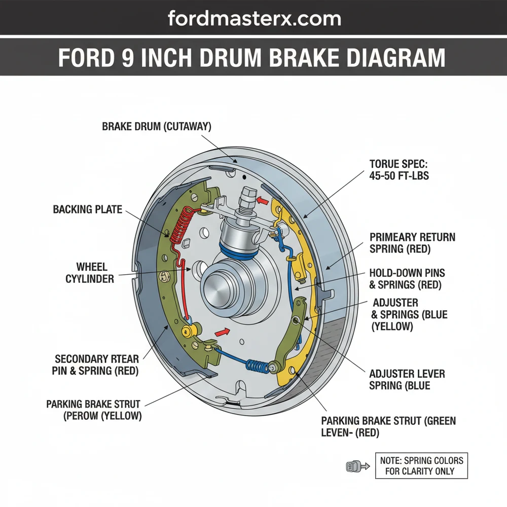
The ford 9 inch drum brake diagram reveals a sophisticated mechanical system designed to convert hydraulic pressure into friction. At the heart of the system is the backing plate, which bolts directly to the axle flange. Mounted to this plate is the wheel cylinder, the primary hydraulic actuator. When you press the brake pedal, the wheel cylinder pistons push outward against the brake shoes.
The diagram identifies two distinct shoes: the primary shoe and the secondary shoe. A crucial detail often missed by beginners is that the primary shoe (which has a shorter lining) always faces the front of the vehicle, while the secondary shoe (with the longer lining) faces the rear. This orientation is vital because the secondary shoe does most of the braking work due to the “self-energizing” effect created by the rotation of the drum.
Connecting these components is a web of springs and linkages. The return springs pull the shoes back to their resting position when pressure is released, while the hold-down pins and cups keep the shoes flush against the backing plate. At the bottom, you will find the star wheel adjuster and the adjuster cable. This mechanism is designed to automatically expand the shoes as the friction material wears down, maintaining a consistent pedal feel. Because these parts are subjected to extreme heat and road debris, they often correlate with mechanical wear seen in other parts of the vehicle, such as the accessory belt or water pump bearings, which also require periodic inspection.
[DIAGRAM_PLACEHOLDER: EXPLODED VIEW OF FORD 9-INCH DRUM BRAKE ASSEMBLY]
Labels: 1. Wheel Cylinder | 2. Primary Shoe (Front) | 3. Secondary Shoe (Rear) | 4. Return Springs | 5. Hold-down Pins | 6. Star Wheel Adjuster | 7. Parking Brake Lever | 8. Adjuster Cable
How to Read and Interpret the Diagram for Installation
Reading a ford 9 inch drum brake diagram requires an understanding of perspective and layering. The diagram usually presents an “exploded” view, meaning the parts are pulled away from each other along a central axis to show where they fit relative to one another. To translate this to your vehicle, follow these logical steps to ensure a perfect rebuild.
- ✓ Step 1: Preparation and Safety. Ensure the vehicle is securely supported on jack stands. Remove the rear wheels and the brake drums. If the drum is stuck, use a rubber mallet to vibrate it loose. Never breathe in brake dust, as older linings may contain hazardous materials.
- ✓ Step 2: Component Identification. Layout your new parts and compare them to the diagram. Verify that you have the correct primary and secondary shoes. Ensure the wheel cylinder is clean and free of leaks. If your vehicle uses a modern swap, ensure your ECU is not reporting any ABS-related issues that might interfere with manual brake testing.
- ✓ Step 3: Mounting the Shoes. Apply a small amount of high-temperature brake grease to the contact points on the backing plate. Position the primary shoe toward the front and the secondary toward the rear. Secure them using the hold-down pins and springs as shown in the ford 9 inch drum brake diagram.
- ✓ Step 4: Installing the Wheel Cylinder and Springs. Connect the tops of the shoes to the wheel cylinder pins. Attach the return springs. These are often color-coded; typically, the heavier spring goes on the secondary shoe side. Use a dedicated brake spring tool to avoid injury or damage to the springs.
- ✓ Step 5: The Adjuster Mechanism. Install the star wheel adjuster at the bottom of the shoes. The diagram will show the orientation of the “teeth” on the star wheel. Ensure the adjuster cable is routed over the guide plate and hooked into the self-adjuster lever properly.
- ✓ Step 6: Parking Brake Integration. Attach the parking brake lever to the secondary shoe. This is held in place by a specialized clip and wave washer. Ensure the cable moves freely through the backing plate housing.
- ✓ Step 7: Final Inspection and Drum Fitting. Compare your finished work one last time to the diagram. Slide the drum over the shoes. If it doesn’t fit, turn the star wheel to retract the shoes. Once the drum is on, adjust the star wheel until you feel a slight drag when turning the drum by hand.
- ✓ Step 8: Torque Spec and Testing. Reinstall the wheels and tighten the lug nuts to the manufacturer’s torque spec. Before driving, pump the brake pedal several times to seat the shoes against the drum.
Do not attempt to operate the vehicle if the brake pedal feels “spongy.” This indicates air in the lines or a mechanical misalignment. Always bleed the brakes starting from the wheel furthest from the master cylinder to ensure no air remains in the system.
Common Issues and Troubleshooting with the Ford 9-Inch System

Even with a perfect ford 9 inch drum brake diagram, issues can arise during or after installation. One frequent problem is “brake drag,” where the shoes do not fully retract. This is often caused by installing the return springs in the wrong holes or using an adjuster that is seized. If you notice excessive heat coming from the rear wheels after a drive, the self-adjuster may be over-tightening.
Another common issue is uneven braking or “pulling” to one side. This is usually the result of a leaking wheel cylinder or contaminated brake linings. If brake fluid touches the shoe material, the shoe must be replaced; it cannot be cleaned. In modern applications where a Ford 9-inch is swapped into a newer vehicle, a malfunctioning rear brake system might trigger a check engine light or a specific diagnostic code if the vehicle’s computer detects a discrepancy in wheel speed through the OBD-II port. While the 9-inch is mostly mechanical, its interaction with the rest of the vehicle’s safety systems is paramount.
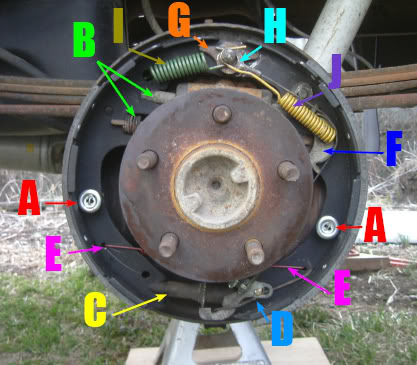
Take a photo of the assembled brakes on the opposite side of the car before you start. Since drum brakes are mirrored, the passenger side will be the reverse of the driver side, but the component relationships remain the same. This provides a real-world reference to complement your diagram.
Tips and Best Practices for Long-Term Performance
To maintain the longevity of your Ford 9-inch rear brakes, consistency in maintenance is key. Just as you would monitor your coolant flow to prevent engine overheating or listen for a rattling timing chain, you should periodically inspect your drum brakes for shoe wear and hardware fatigue.
First, always use high-quality hardware kits. The heat cycles experienced by brake springs eventually cause them to lose their tension. Replacing the springs every time you replace the shoes is a cost-effective way to ensure the system remains responsive. Second, ensure that your backing plates are not grooved. Over time, the shoes can wear “ruts” into the contact points of the backing plate, causing the shoes to hang up. These can often be smoothed out with a file and a dab of specialized brake lubricant.
If you are performing a full vehicle service, take this time to inspect the front of the vehicle as well. Check the condition of the accessory belt and look for any leaks around the water pump or radiator hoses. While the Ford 9-inch is located at the rear, the overall safety of your car depends on a holistic approach to maintenance. Using an OBD-II scanner to check for a diagnostic code related to the braking or traction control systems can also reveal hidden issues that a physical inspection might miss.
Finally, remember that the Ford 9-inch is a heavy-duty component. If you are using it for towing or racing, consider upgrading to metallic or ceramic shoe compounds that can handle higher thermal loads. By following the ford 9 inch drum brake diagram and adhering to these best practices, you ensure that one of the most vital safety systems on your vehicle remains in peak operating condition for years to come.
Frequently Asked Questions
Where is the wheel cylinder located?
The wheel cylinder is located at the top of the backing plate, between the upper ends of the brake shoes. It receives hydraulic pressure from the master cylinder to push the shoes outward. If you notice leaks here, it can contaminate the shoes and reduce overall braking performance significantly.
What does the drum brake diagram show?
The diagram shows the intricate layout of the 9-inch rear brake assembly, including the springs, pins, and levers. It specifically highlights how the self-adjuster cable wraps around the anchor pin and connects to the adjuster lever, ensuring the shoes remain at the proper distance from the drum surface.
How many springs does the Ford 9 inch assembly have?
A standard Ford 9 inch assembly typically features two large return springs at the top, two hold-down springs with pins and cups, and one adjuster spring at the bottom. The diagram helps identify which spring color or length belongs on the primary versus the secondary side for correct tension.
What are the symptoms of a bad drum brake?
Symptoms include pulling to one side, a low pedal, or grinding noises. If your vehicle uses an ABS retrofit, a mechanical failure might trigger a check engine light. Use an OBD-II scanner to check for a diagnostic code related to wheel speed sensors, as mechanical drag affects sensor data.
Can I replace the drum brakes myself?
Yes, you can replace them yourself with patience and a clear diagram. It is a classic DIY project that requires basic mechanical skills. Working on one side at a time is recommended so you can use the other side as a three-dimensional reference alongside the printed assembly diagram.
What tools do I need for this rebuild?
You will need brake spring pliers, a flathead screwdriver, and a drum adjustment tool. A torque wrench is also necessary to meet the required torque spec for the lug nuts and backing plate bolts. This ensures that the ECU receives stable wheel speed input if your axle has sensors.


