Ford 6.8 V10 Engine Diagram: Complete Identification Guide
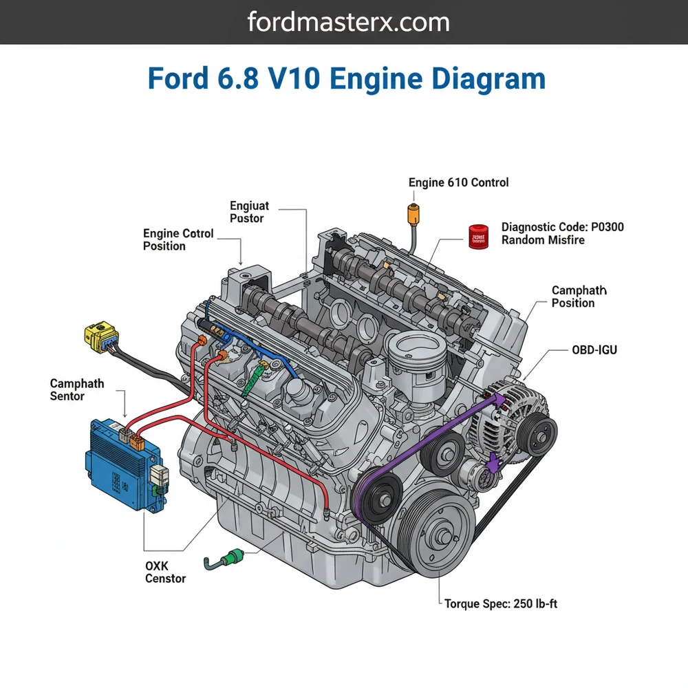
The Ford 6.8 V10 engine diagram provides a visual layout of the SOHC modular engine, including the intake manifold, fuel rails, and COP ignition system. It is vital for locating sensors and the ECU during troubleshooting. By following this map, you can effectively diagnose a check engine light or perform critical maintenance tasks.
📌 Key Takeaways
- Provides a visual roadmap for all major internal and external engine components.
- Crucial for identifying the 10 individual ignition coils and fuel injectors.
- Always adhere to the specific torque spec for spark plugs to avoid cylinder head damage.
- Use the diagram to trace vacuum lines and electrical harnesses to the ECU.
- Utilize this guide when a check engine light appears to narrow down component failure.
The Ford 6.8L Triton V10 is a legendary workhorse that has powered Ford’s heaviest-duty vehicles for over two decades. Introduced in 1997 as part of the Modular engine family, this powerhouse found its home in the F-250, F-350, Ford Excursion, and the ubiquitous E-Series vans. For the DIY enthusiast, understanding the 6.8 V10 engine diagram is the first step in maintaining, repairing, or upgrading this complex piece of machinery. Whether you are dealing with the earlier 2-valve version or the later 3-valve variant, having a clear mental and physical map of the engine bay is essential for navigating the tight clearances of a Super Duty or the cramped engine tunnel of an Econoline.
Main Components and Features
The 6.8L V10 is essentially a 5.4L V8 with two extra cylinders added. However, those extra cylinders bring specific layout considerations. To read a diagram effectively, you must first identify the primary systems and their physical locations.
1. Cylinder Layout and Firing Order:
Unlike some manufacturers that alternate numbers from side to side, Ford numbers its cylinders sequentially. When standing at the front of the vehicle looking at the engine:
- Bank 1 (Passenger Side): Cylinders 1, 2, 3, 4, 5 (Front to Back).
- Bank 2 (Driver Side): Cylinders 6, 7, 8, 9, 10 (Front to Back).
- Firing Order: 1-6-5-10-2-7-3-8-4-9.
Understanding this numbering is critical when a diagnostic tool reports a “Misfire on Cylinder 7” or “Oxygen Sensor Bank 2.”
2. Ignition System (COP):
The V10 uses a Coil-on-Plug (COP) ignition system. Each cylinder has its own individual coil pack sitting directly on top of the spark plug. The wiring harness for these coils runs along the fuel rails.
- Wire Colors: Typically, each coil has a Red/Light Green wire (hot) and a unique color-coded wire for the PCM trigger. For example, Cylinder 1 often uses a Light Blue/White wire, while Cylinder 10 might use a Dark Green/Light Green wire.
3. Serpentine Belt Routing:
The belt diagram is usually found on a sticker on the radiator shroud, but it is often missing on older trucks. The path includes the crankshaft pulley (bottom center), water pump (center), alternator (top), power steering pump (lower driver side), and the A/C compressor (lower passenger side). There are also two idler pulleys and one spring-loaded tensioner. Using a 1/2-inch drive breaker bar on the tensioner is the standard method for removal.
4. Intake and Vacuum System:
The intake manifold is a massive cast aluminum or composite structure. On the 3-valve engines, it features Charge Motion Control Valves (CMCV) at the rear. The vacuum system is notorious for a “Y-pipe” connector located behind the throttle body which frequently rots, causing lean codes (P0171/P0174).
How to Use and Read an Engine Diagram
Reading a Ford 6.8 V10 diagram requires understanding the distinction between a “Component Location Diagram,” a “Vacuum Map,” and a “Wiring Schematic.”
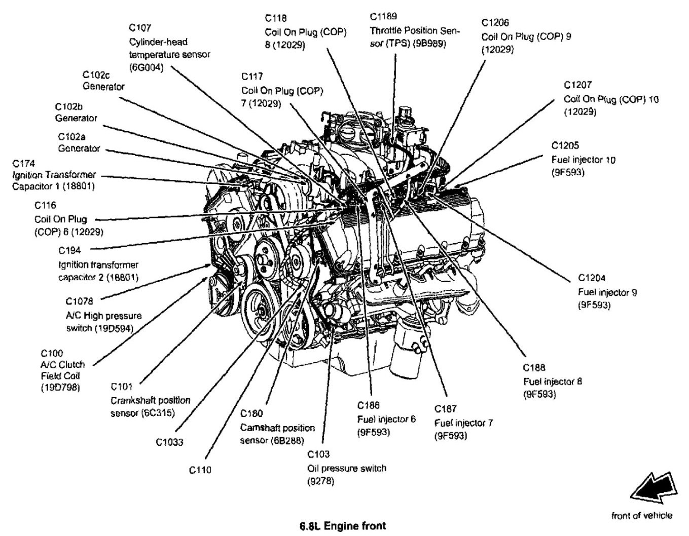
1. Component Location Diagrams:
These are 3D-rendered or line-drawing views of the engine. Use these to find sensors. For instance, the Crankshaft Position (CKP) Sensor is located on the front cover, behind the A/C compressor on the passenger side. The Camshaft Position (CMP) Sensor is located on the front of the driver-side cylinder head. If you are looking at a diagram and can’t find a part, look for “hidden” lines which indicate components tucked under the intake plenum.
2. Vacuum Maps:
Look for the legend. Solid lines usually represent hard plastic lines, while dashed lines represent rubber hoses. On the V10, pay close attention to the line running to the PCV (Positive Crankcase Ventilation) valve on the passenger side valve cover and the EVAP canister purge valve located on the driver side inner fender or firewall.
3. Electrical Schematics:
Ford uses a standardized color-coding system. In a diagram, a wire labeled “BK/WH” means Black with a White stripe. On the V10, the fuel injector harness and the COP harness are frequently confused. Reference the diagram to ensure you haven’t swapped the connectors for the rear-most cylinders (5 and 10) during a manifold repair.
Maintenance and DIY Tips

Working on a V10 requires specialized knowledge, particularly regarding the spark plugs and exhaust manifolds—the two most common “headaches” for this engine.
Spark Plug Replacement:
Early 2-valve heads (pre-2002) only had about 4 threads holding the spark plugs in, leading to the infamous “plug blowout” issue. Later 3-valve engines (2005+) had a different issue where the two-piece spark plugs would seize and break off in the head.
- 2-Valve Tip: Torque spark plugs to 28-30 ft-lbs (dry). This is higher than the original Ford spec but is widely accepted by the DIY community to prevent blowouts.
- 3-Valve Tip: Use a specialized spark plug removal tool (like the Lisle 65600) before you start, just in case a plug breaks. Apply nickel anti-seize only to the smooth shank of the plug, not the threads.
Oil and Fluids:
The 6.8 V10 requires 6 quarts of 5W-20 or 5W-30 synthetic blend oil, depending on the year. Because this is an overhead cam (OHC) engine, oil pressure is vital for the timing chain tensioners. Use only high-quality Motorcraft filters with a silicone anti-drainback valve to prevent “dry starts” that can lead to timing chain guide wear.
Cooling System:
The V10 holds a massive amount of coolant (roughly 27-30 quarts). When refilling, you must use the degas bottle to bleed air. If you see a diagram showing a “heater bypass valve,” check its vacuum line; if it fails, your A/C will struggle to stay cool because hot coolant is constantly flowing through the heater core.
Troubleshooting Common Issues Using the Diagram
When the Check Engine Light (CEL) comes on, your diagram becomes a diagnostic map. Here is how to approach the most common V10 failures:
1. P0171 and P0174 (System Lean):
These codes usually point to a vacuum leak. Refer to your vacuum diagram and inspect the PCV “elbow” at the back of the intake manifold. This rubber piece often develops a crack on the underside where you can’t see it. Use a mirror or your hand to feel for soft, mushy rubber or a sucking sound.
2. P0300-P0310 (Misfire Codes):
If you have a P0307, the diagram tells you that is the second cylinder from the front on the driver’s side.
- Swap the coil from cylinder 7 to cylinder 6.
- If the code changes to P0306, the coil is bad.
- If the code stays at P0307, check the wiring harness diagram for a break in the trigger wire or inspect the spark plug.
3. Exhaust Manifold Leaks:
The V10 is notorious for snapping exhaust manifold studs, particularly on the rear cylinders (5 and 10). This creates a loud “ticking” sound that mimics a lifter knock. If you look at an engine diagram of the exhaust side, you will see 10 studs per side. If the rear-most stud is missing its nut, you have found your leak. Replacing these often requires removing the inner fender liners for access.
4. Low Power/Stalling:
Check the Fuel Pump Driver Module (FPDM) located on the frame rail near the spare tire (on F-series trucks). While not physically on the engine, it is part of the engine’s electrical diagram. These modules rot out due to road salt, cutting power to the fuel injectors.
- Keep a copy of the firing order and cylinder numbering in your toolbox.
- Always use a torque wrench on spark plugs and intake bolts.
- Clean the MAF (Mass Air Flow) sensor every 30,000 miles to maintain fuel economy.
- Inspect the “hidden” vacuum lines at the rear of the block every oil change.
The Ford 6.8L V10 is a remarkably resilient engine if the basic systems are understood. By using an engine diagram to locate sensors, trace vacuum lines, and identify cylinder banks, the DIY enthusiast can keep these high-torque giants on the road for 300,000 miles or more. Whether you’re towing a 30-foot trailer or driving a converted camper van, knowing your way around the Triton V10 is the best insurance against expensive shop bills.
Step-by-Step Guide to Understanding the Ford 6.8 V10 Engine Diagram: Complete Identification Guide
Identify – Start with identifying the front-of-engine components like the alternator, water pump, and fan clutch assembly.
Locate – Locate the intake plenum and fuel rails to understand the upper engine architecture and vacuum line routing.
Understand – Understand how the ECU interacts with various sensors across the engine block via the main wiring loom.
Connect – Connect an OBD-II scanner to the vehicle port to pull any active diagnostic code causing performance issues.
Verify – Verify the specific torque spec for every fastener during reassembly to ensure engine longevity and prevent leaks.
Complete – Complete the inspection by cross-referencing the serpentine belt routing diagram to ensure proper tensioner alignment.
Frequently Asked Questions
Where is the ECU located on a Ford 6.8 V10?
The ECU, or Powertrain Control Module, is typically located on the passenger side firewall or behind the interior kick panel. The engine diagram shows the harness routing that leads from the engine sensors directly to this central controller, which manages fuel injection and ignition timing for all ten cylinders.
What does this engine diagram show?
This diagram illustrates the comprehensive layout of the 6.8L Triton V10 engine. It highlights the location of the intake manifold, throttle body, alternator, and power steering pump. It also maps out the serpentine belt routing and the positioning of critical sensors like the MAF and O2 sensors.
How many ignition coils does the V10 have?
The Ford 6.8 V10 uses a Coil-On-Plug (COP) system, meaning it has 10 individual ignition coils. Each coil is connected to a spark plug located deep within the cylinder head. The diagram helps identify the cylinder numbering sequence, which is essential when diagnosing a specific cylinder misfire.
What are the symptoms of a bad V10 sensor?
Common symptoms include a rough idle, reduced fuel economy, or a persistent check engine light. Using an OBD-II scanner will often reveal a specific diagnostic code related to the MAF, TPS, or oxygen sensors, which you can then locate on the engine diagram for inspection or replacement.
Can I replace the spark plugs myself?
Yes, spark plug replacement is a common DIY task, but it requires extreme caution. Early V10 models are known for spark plug blowout issues, while later 3-valve models may have plugs that break. Always use a torque wrench to meet the exact torque spec provided in the service manual.
What tools do I need for engine diagnostics?
To perform basic diagnostics, you will need a high-quality OBD-II scanner to read codes. For physical repairs, a standard metric socket set, a torque wrench, and long-reach spark plug sockets are necessary. The engine diagram serves as your primary reference for where to apply these tools safely.


