Ford 5.4 Heater Hose Diagram: System Layout Guide
A Ford 5.4 heater hose diagram displays the complex routing between the engine’s water pump and the heater core at the firewall. This layout includes the supply and return lines, highlighting critical components like quick-connect fittings. Studying this configuration is essential for identifying coolant leaks and ensuring the heating system functions correctly.
📌 Key Takeaways
- Visualizes the flow between the engine structure and heater core
- Identifies the supply vs. return hose connections
- Highlights the importance of specialized quick-disconnect fittings
- Pinpoints common leak areas near the intake manifold junction
- Essential for accurate part identification and DIY replacement
Understanding the cooling system architecture of the Ford 5.4L V8 engine is a critical skill for any truck or SUV owner who prefers DIY maintenance. Whether you are dealing with a mysterious coolant leak or a complete lack of cabin heat during the winter, having a clear ford 5.4 heater hose diagram is the only way to navigate the cramped engine bay effectively. This specific engine, known for its longevity and power, features a cooling system that relies on precise hose routing to move hot coolant from the engine block to the heater core and back again. By mastering this layout, you can identify failure points before they lead to engine overheating. In this guide, you will learn how to interpret the routing schematic, identify every relevant component, and follow a professional process for hose replacement and system bleeding.
Main Diagram Description and Component Layout
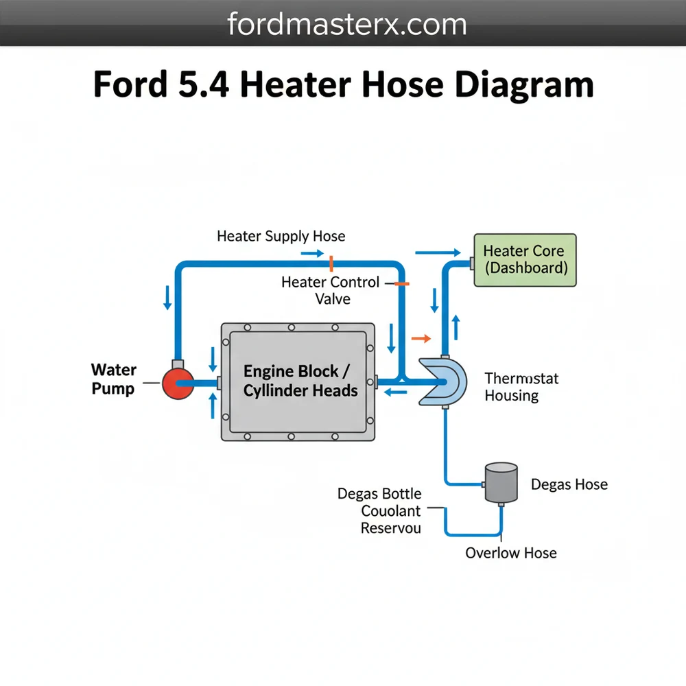
The ford 5.4 heater hose diagram represents a closed-loop system designed to transfer thermal energy from the engine to the vehicle’s interior. This configuration consists of several distinct sections that work in tandem to maintain engine temperature while providing climate control. At the heart of the blueprint are the two primary hoses: the supply (inlet) hose and the return (outlet) hose.
The supply hose typically originates from the rear of the intake manifold or the cylinder head, depending on the specific engine revision. This line carries the hottest coolant directly into the heater core located behind the dashboard on the passenger side. In the schematic, this is often represented as the “High-Pressure Side.” The return hose then exits the heater core and travels back toward the engine, usually connecting to a metal bypass tube or directly to the water pump housing.
Most Ford 5.4L engines utilize “Quick-Connect” fittings at the firewall. These plastic connectors are designed for fast assembly but are a common failure point as they become brittle over time. A diagram will help you identify which specific connector type your model uses.
Visualizing the structure requires looking at the engine from the front. The heater hoses are located on the passenger side of the engine bay, snaking along the top of the valve cover toward the firewall. The layout is often color-coded in technical manuals: red for the hot supply line and blue for the cooler return line. Variations in the configuration may exist for vehicles equipped with rear climate control, which adds a secondary “T-junction” and additional lines running toward the rear of the chassis.
How to Read and Interpret the Schematic

Reading a ford 5.4 heater hose diagram is different from looking at a photograph of an engine. The schematic focuses on the “path of flow” rather than the physical size of the components. To use the diagram effectively during a repair, you must translate the lines on the page to the physical hoses in your engine bay.
- 1. Locate the Firewall Junction: Start by identifying the two nipples protruding from the passenger-side firewall. These are the entry and exit points for the heater core. On your diagram, these are usually marked as “Inlet” and “Outlet.”
- 2. Trace the Supply Line: Follow the hose from the firewall back to the engine. In the 5.4L configuration, it usually connects to a fitting on the rear of the intake manifold. This hose is responsible for bringing heat into the cabin.
- 3. Identify the Return Path: The second hose from the firewall will lead toward the front of the engine. It often attaches to a long metal tube that runs under the intake manifold or alongside the valve cover, eventually feeding back into the water pump.
- 4. Check for Auxiliary Components: If your diagram shows a “T” or “Y” connector, your vehicle has rear heat. Ensure you are tracing the correct branch for the section you are servicing.
- 5. Verify Clamp Types: The schematic will often note whether a constant-tension spring clamp or a screw-type clamp is used. Make sure you have the appropriate pliers for the spring clamps.
Never attempt to disconnect heater hoses while the engine is hot. The 5.4L cooling system is pressurized, and opening a hose can result in severe burns from scalding coolant spray.
Step-By-Step Heater Hose Replacement Guide

Once you have studied the ford 5.4 heater hose diagram and identified the parts, follow these steps to perform a professional-grade replacement.
Tools Needed:
- ✓ Quick-disconnect tool set (specifically for Ford fittings)
- ✓ Long-reach needle-nose pliers
- ✓ Coolant drain pan
- ✓ New Ford-spec coolant (Gold or Orange depending on your specific manual)
- ✓ Shop towels and safety glasses
The Process:
1. Drain the System: Place your drain pan under the radiator petcock. Open the radiator cap (when cold) and the petcock to drain about one to two gallons of coolant. You do not need to drain the entire block, just enough to lower the level below the heater hoses.
2. Disconnect at the Firewall: This is often the hardest part. Use your quick-disconnect tool to depress the internal tabs of the plastic heater hose fittings at the firewall. Pull the hose away from the heater core gently. If the connector is stuck, do not pry against the heater core nipples, as they are thin aluminum and easily damaged.
3. Disconnect at the Engine: Use pliers to slide the spring clamps back on the engine side of the hoses. Carefully twist the hose to break the seal before pulling it off the manifold or water pump tube.
4. Install the New Hoses: Compare your new hoses to the old ones and the ford 5.4 heater hose diagram to ensure proper orientation. Click the quick-connect ends onto the heater core first; you should hear an audible “click” when they seat properly. Then, attach the engine-side ends and secure them with clamps.
5. Refill and Bleed: This is the most critical step for the 5.4L engine. Refill the degas bottle with a 50/50 coolant mix. Start the engine with the heater on full blast. As the engine warms up, the thermostat will open, and air bubbles will work their way to the degas bottle. Keep the bottle topped off until the level stabilizes and you have consistent heat from the vents.
If you are having trouble removing an old hose from a metal nipple, use a dedicated hose-removal pick to break the “vulcanized” bond. A small amount of silicone spray on the inside of the new hose will make installation much easier.
Common Issues and Troubleshooting
The 5.4L Triton engine is known for a few specific heater hose issues that can be easily diagnosed using the ford 5.4 heater hose diagram as a reference point.
Plastic Connector Failure: The most frequent issue is a leak at the firewall. The plastic quick-connects fail due to heat cycling. If you see white crusty residue or dripping on the passenger side firewall, these connectors are the likely culprit.
The “Hidden” Leak: Sometimes coolant will pool in the spark plug wells of the 5.4L engine, causing a misfire. While many assume this is a head gasket issue, it is often a tiny pinhole leak in the heater hose or the intake manifold fitting. By tracing the hose path on your schematic, you can see how a leak in the supply line can drip directly into the engine’s valley or plug wells.
Air Pockets: If you have recently replaced a hose and now have no heat, you likely have an air lock. The heater core sits high in the engine bay, making it a natural trap for air. Use the diagram to identify the highest point in the system and ensure the air is properly purged.
Best Practices for Long-Term Maintenance
To avoid emergency repairs, proactive maintenance of your heater hose system is essential. The hoses on a Ford 5.4L generally have a lifespan of 100,000 to 150,000 miles. Beyond this point, the rubber becomes spongy or excessively brittle.
- ✓ Inspect Monthly: Squeeze the hoses when the engine is cold. They should feel firm but flexible. If they feel crunchy or “soft like a marshmallow,” replace them immediately.
- ✓ Use OE-Spec Components: While universal hoses are cheaper, the 5.4L uses specifically molded bends. Using a universal hose can lead to kinking, which restricts flow and reduces heater efficiency.
- ✓ Check the Metal Return Tube: On many 5.4L configurations, the return hose connects to a metal tube in the engine valley. This tube can rust from the outside in. If you are doing a major service, inspect this pipe for signs of corrosion.
- ✓ Flush Regularly: Changing your coolant every 50,000 miles prevents the buildup of sediment that can clog the heater core and cause the hoses to deteriorate from the inside out.
In conclusion, maintaining your vehicle with the help of a ford 5.4 heater hose diagram ensures that your engine remains cool and your cabin remains warm. By understanding the layout, following a systematic replacement process, and keeping an eye out for common failure points like the quick-connect fittings, you can significantly extend the life of your Ford truck or SUV. Always prioritize safety and use high-quality parts to maintain the integrity of your cooling system.
Step-by-Step Guide to Understanding the Ford 5.4 Heater Hose Diagram: System Layout Guide
Identify the supply and return lines in the Ford 5.4 heater hose diagram to understand the coolant flow direction.
Locate the heater core nipples protruding from the passenger side firewall where the hoses attach to the cabin.
Understand how the quick-connect fittings lock onto the heater core tubes to avoid breaking the plastic clips.
Connect the new hoses by pushing them firmly onto the fittings until you hear or feel a positive click.
Verify that the hose routing doesn’t interfere with the fuel rail or electrical wiring in the engine bay.
Complete the installation by refilling the coolant reservoir and running the engine to bleed out any trapped air.
Frequently Asked Questions
Where is the heater hose located?
The heater hoses on a Ford 5.4L engine are located at the rear of the engine compartment, running from the intake manifold and water pump area toward the passenger side firewall. They connect directly to the heater core inlets and outlets to circulate warm coolant into the vehicle’s cabin structure.
What does this diagram show?
The Ford 5.4 heater hose diagram shows the specific routing, pathing, and connection points for the heater supply and return lines. It illustrates how coolant moves through the engine system into the heater core, helping users visualize the layout and identify specific hose part numbers or connection locations.
How many connections does this system have?
Most Ford 5.4 heater hose systems feature two main lines: the inlet and outlet. Each hose typically has two connection points—one at the engine (intake manifold or water pump) and one at the firewall. This configuration may include auxiliary lines if the vehicle is equipped with a rear heating system.
What are the symptoms of a bad heater hose?
Symptoms of a failing Ford 5.4 heater hose include visible coolant puddles under the truck, a sweet maple syrup smell inside the cabin, or the heater blowing cold air. You may also notice engine overheating or white crusty deposits near the hose’s quick-connect fittings or hose clamp areas.
Can I replace this myself?
Replacing heater hoses on a Ford 5.4 is a manageable DIY task for most owners. The most difficult part is often reaching the connections at the firewall. Using a specialized quick-disconnect tool can significantly simplify the process and prevent damage to the heater core tubes during the removal component.
What tools do I need for this task?
To work on these hoses, you will need basic hand tools like pliers for spring clamps and a screwdriver. A Ford-specific heater hose disconnect tool is highly recommended for the quick-connect fittings. Additionally, have a drain pan, fresh coolant, and rags ready to manage any spilled engine fluid.


