Ford 4 Pin Relay Wiring Diagram: Easy Setup Guide
A Ford 4 pin relay diagram illustrates how the powertrain control module triggers power to specific trailer circuits. Pins 85 and 86 control the relay coil, while pins 30 and 87 complete the high-current circuit for auxiliary power, turn signals, or running lights, ensuring safe power distribution to your trailer.
📌 Key Takeaways
- Identifies the switching logic for Ford trailer tow circuits
- Pin 30 is the primary fused power source from the battery
- Proper grounding is essential to prevent circuit flickering
- Multimeter testing is required to confirm signal output
- Necessary for converting or repairing an RV blade connector
When you are preparing to tow a heavy trailer or a camper with your Ford vehicle, ensuring that the electrical connection between the truck and the trailer is seamless becomes a top priority for safety and functionality. Ford vehicles utilize a specific power distribution system where relays act as the gatekeepers for high-current circuits. Understanding a ford 4 pin relay diagram is essential for diagnosing why your trailer lights might be flickering or why your battery isn’t charging while in transit. This guide provides a comprehensive breakdown of the relay’s internal logic, the wiring harness interface, and how to verify that power is flowing correctly to your flat connector or RV blade socket. By the end of this article, you will have the technical confidence to install, test, and repair your Ford’s trailer relay system.
Understanding the Ford 4 Pin Relay Diagram and Components
The 4-pin relay found in the Ford Power Distribution Box is a relatively simple electromagnetic switch, but its role is critical. In a trailer application, these relays are typically responsible for managing auxiliary power, running lights, or the electric brake signal. The relay allows a low-current signal from your dash switch or computer to trigger a much higher current directly from the battery to the trailer.
A standard Ford 4-pin relay diagram identifies four specific terminals, often labeled using the international standard ISO numbering:
- ✓ Pin 30 (Common/Battery Power): This is the constant 12V input directly from the vehicle battery, usually protected by a high-amperage fuse.
- ✓ Pin 87 (Load/Output): This pin sends the power out to the trailer connector when the relay is activated.
- ✓ Pin 85 (Ground): This connects to the vehicle chassis to complete the circuit for the internal electromagnetic coil.
- ✓ Pin 86 (Trigger/Switch): This pin receives a small amount of current when you turn on your lights or tap the brakes, which “closes” the relay switch.
In Ford trucks, these relays are housed in the engine bay fuse box. The diagram usually shows these pins in a specific layout: two pins are parallel to each other, while the other two are perpendicular or offset. While the physical orientation might change slightly between different Ford models, the logic remains identical. The diagram helps you identify which slot in the fuse box corresponds to which function, such as the left/right turn signal or the brake controller output.
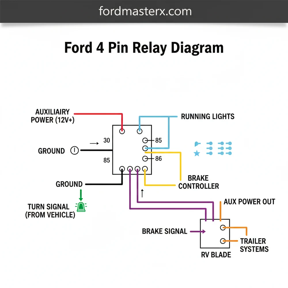
[DIAGRAM_PLACEHOLDER: A visual representation of a Ford 4-pin relay showing Pin 30, 87, 85, and 86. The diagram illustrates Pin 30 connected to the battery, Pin 87 leading to the 7-way RV blade connector, Pin 85 to the ground pin, and Pin 86 connected to the vehicle’s signal switch.]
Most Ford trucks are pre-wired for towing, but the actual relay for the 12V auxiliary power and the electric brake controller is often left in the glovebox or a plastic bag from the factory. You must physically install the relay into the Power Distribution Box to enable charging for your trailer battery.
Step-by-Step Guide: Interpreting and Installing the Relay

Reading a ford 4 pin relay diagram is the first step toward a successful DIY installation or repair. Follow these steps to ensure your trailer’s electrical system is operating at peak performance.
Step 1: Locate the Power Distribution Box
Open your vehicle’s hood and locate the primary fuse box, usually positioned near the battery or the driver-side fender. Consult your owner’s manual to find the specific “Trailer Tow Relay” locations. Ford often uses separate relays for the left turn, right turn, and backup lamps.
Step 2: Identify the Relay Pins
Look at the bottom of the relay. You will see numbers (30, 85, 86, 87) embossed next to the metal tangs. If you are looking at the fuse box itself, the diagram on the underside of the fuse box cover will show you which orientation the relay should take. Ensure the pins line up with the slots in the distribution box.
Step 3: Test for Battery Constant (Pin 30)
Using a multimeter set to DC Volts, place the black lead on a bare metal part of the frame and the red lead into the slot for Pin 30. You should read approximately 12.4V to 12.6V. This confirms that the fuse leading to the relay is intact. If there is no power here, check the “Trailer Tow” maxi-fuses first.
Step 4: Verify the Trigger Signal (Pin 86)
To see if the vehicle is actually telling the relay to turn on, have an assistant turn on the running lights or the turn signal. Test the slot for Pin 86. It should show 12V only when the corresponding light is active. This confirms your vehicle’s computer or switch is sending the correct signal.
Step 5: Check the Ground (Pin 85)
Switch your multimeter to the “Continuity” setting (the one that beeps). Place one probe in the Pin 85 slot and the other on a clean ground pin or chassis bolt. A beep indicates a solid ground. Without a good ground, the relay’s internal coil cannot pull the switch closed.
Step 6: Confirm Output to the Trailer Plug
Once the relay is inserted, move to the back of the truck. Use a circuit tester on the RV blade or 4-way flat connector. Check the pins for the corresponding function you just tested. For example, if you installed the auxiliary power relay, the 12V charging pin on the trailer plug should now be “hot.”
Never bypass a relay with a permanent jumper wire for long-term use. Relays are designed to handle high-amperage loads that your dashboard switches cannot. Jumping the circuit can cause the wiring harness to overheat and potentially lead to an electrical fire.
Common Issues and Troubleshooting

Even with a perfect ford 4 pin relay diagram, you may encounter issues. One of the most common complaints is the “relay click.” If you hear the relay clicking but the running lights on the trailer don’t turn on, the internal contact points of the relay may be burnt, or the power supply at Pin 30 might be weak.
Another frequent problem involves the ground pin at the trailer plug itself. Because trailers rely on the hitch ball or a single white wire for grounding, corrosion can break the circuit. If your relay tests fine but the lights are dim or behave erratically (e.g., the turn signal flashes both lights), you almost certainly have a ground issue rather than a relay failure.
If you are using an aftermarket brake controller, ensure it is properly integrated with the Ford wiring harness. An improperly installed controller can send feedback into the relay system, causing the electric brake circuit to stay engaged or fail entirely. When troubleshooting, always test the truck side of the plug first to isolate whether the problem lies within the Ford’s relay system or the trailer’s wiring.
If you are stuck on the side of the road with no trailer lights, you can often temporarily swap a non-essential relay (like the one for the horn or the fog lights) with the trailer relay to get your lights working again, provided they share the same part number and pin configuration.
Tips and Best Practices for Trailer Wiring
To maintain a reliable connection and avoid having to constantly consult your ford 4 pin relay diagram, follow these maintenance best practices:
- ✓ Use Dielectric Grease: Apply a small amount of dielectric grease to the relay pins and the trailer plug terminals. This prevents moisture from causing corrosion and ensures a low-resistance connection.
- ✓ Inspect the RV Blade Connector: The 7-way RV blade socket is prone to collecting road salt and debris. Use a specialized terminal cleaner tool once a season to keep the copper contacts bright.
- ✓ Match Relay Amperage: Not all 4-pin relays are created equal. Ensure the replacement relay matches the amperage rating of the original Ford part (usually 30A or 40A). Using an under-rated relay will cause it to burn out quickly under the load of electric brake magnets.
- ✓ Secure the Wiring: Ensure the harness leading to the flat connector is zipped-tied away from the exhaust pipe and moving suspension parts. Heat and friction are the leading causes of intermittent shorts.
Investing in a high-quality brake controller and ensuring your Ford’s auxiliary power circuit is active will make long-distance towing much safer. By understanding the flow of electricity from the battery through the relay and out to the trailer, you ensure that your vehicle’s sophisticated electrical system remains protected while providing all the power your trailer needs for the road ahead. Whether you’re dealing with a simple 4-pin flat connector or a complex 7-way setup, the ford 4 pin relay diagram is your ultimate roadmap for towing success.
Frequently Asked Questions
Where is the ford 4 pin relay located?
In most Ford trucks and SUVs, these relays are located in the battery junction box under the hood. Look for the power distribution center near the driver’s side fender or firewall. Consult your owner’s manual for the specific fuse and relay positions mapped to your towing system.
What does the ford 4 pin relay diagram show?
This diagram provides a visual map of the internal connections between the trigger and load pins. It identifies how the relay switches high-current power for trailer functions like turn signals and running lights based on signals from the vehicle’s computer or a manual brake controller setup.
How many pins does a Ford trailer relay have?
A standard Ford trailer relay has four pins, typically numbered 30, 85, 86, and 87. Pin 30 provides battery power, pin 87 sends power to the trailer connector, while pins 85 and 86 act as the switch that activates the internal coil via the vehicle’s wiring.
What are the symptoms of a bad trailer relay?
Signs of a faulty relay include trailer lights that won’t turn on, auxiliary power failing to reach the RV blade connector, or turn signals that stay on constantly. You might also notice a clicking sound if the relay is stuck or no sound at all when the circuit is activated.
Can I replace this relay myself?
Yes, replacing a Ford 4 pin relay is a straightforward DIY task that requires no special tools. Simply locate the power distribution box, identify the correct relay based on the diagram, pull the old unit out vertically, and push the new one into the socket until it is seated.
What tools do I need for relay testing?
To test and install a relay using the diagram, you will need a 12V test light or a digital multimeter to check for continuity and voltage. A pair of needle-nose pliers may be helpful for removing stubborn relays from the fuse box without damaging the plastic housing.


