Ford 351 Windsor Engine Diagram: Step-by-Step Guide
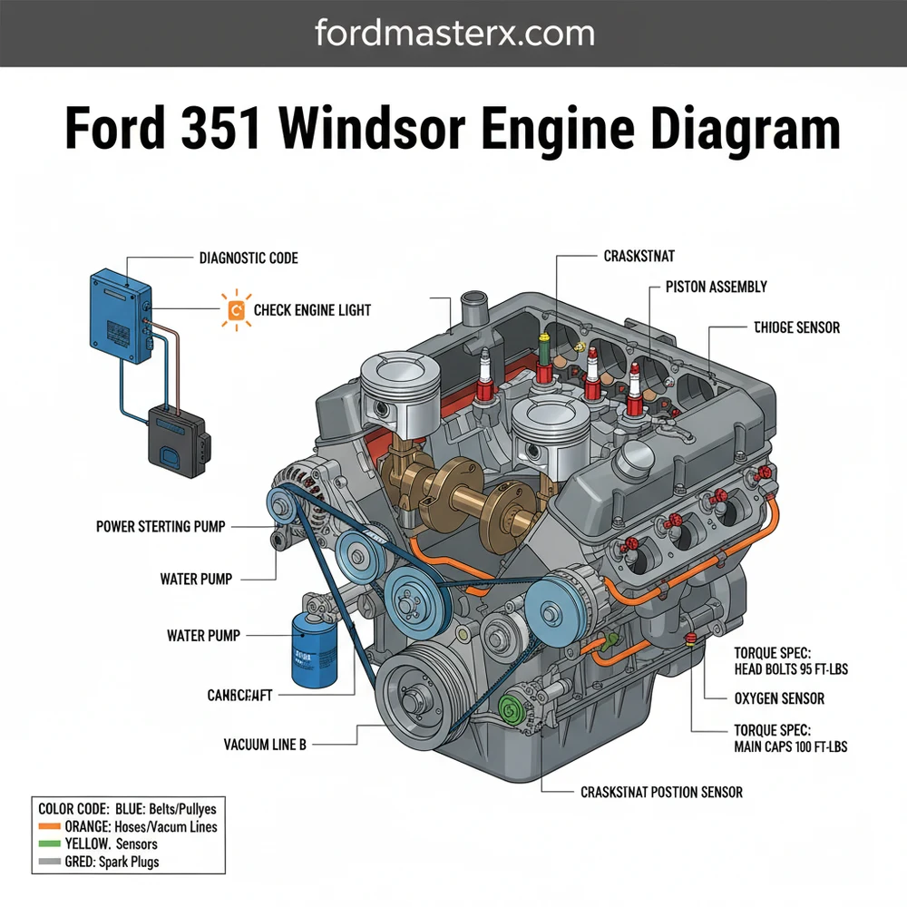
A Ford 351 Windsor engine diagram illustrates the internal and external layout of this small-block V8, highlighting the front-mounted distributor and 6-bolt valve covers. It is essential for identifying the 1-3-7-2-6-5-4-8 firing order and ensuring every head bolt meets the required torque spec during a rebuild or routine maintenance.
📌 Key Takeaways
- Provides a visual map of the V8 internal and external architecture
- Identifies the front-mounted distributor as a key distinguishing feature
- Ensure the battery is disconnected before handling EFI components
- Cross-reference the diagram to verify vacuum routing and firing order
- Use during top-end rebuilds or when diagnosing complex misfires
Navigating the complexities of a classic small-block V8 requires precision, and having a detailed ford 351 windsor engine diagram is the most critical first step for any mechanic or restoration enthusiast. Whether you are performing a simple gasket replacement or an entire frame-off rebuild, the 351 Windsor (351W) presents unique architectural nuances that distinguish it from its smaller sibling, the 302, and its namesake cousin, the 351 Cleveland. This guide is designed to provide you with a comprehensive visual and technical breakdown of the 351W, covering everything from component identification and fluid routing to the specific electrical and mechanical integration necessary to keep this legendary powerplant running smoothly. By the end of this article, you will have a professional-level understanding of how to interpret these diagrams to solve common mechanical hurdles.
The 351 Windsor engine diagram is a visual map that details the physical relationship between the engine’s internal rotating assembly and its external bolt-on components. At the center of the diagram is the block itself, characterized by its 9.5-inch deck height, which is significantly taller than the 302’s 8.2-inch deck. This height difference is a key identifier in any diagram, as it necessitates a wider intake manifold and longer pushrods. The diagram highlights the front-mounted distributor, a hallmark of the Windsor family, which is driven by the camshaft and positioned at the very front of the intake valley.
Another vital element in the diagram is the cooling system architecture. You will see the water pump mounted centrally on the timing cover, with the thermostat housing located on the front of the intake manifold. Unlike the Cleveland engine, which routes coolant through the block and into the heads via internal passages, the Windsor diagram shows the coolant passing through the intake manifold crossover.
For those working on later models, the diagram will also include the electronic fuel injection (EFI) harness, showing the placement of the fuel injectors, the throttle body, and various sensors like the MAP or MAF sensors. Color-coding in modern diagrams often distinguishes between high-pressure oil galleries (usually red), coolant passages (blue), and vacuum lines (green or black). Understanding these distinctions is essential for identifying potential leak points or misrouted hoses that could lead to engine failure.
The 351 Windsor uses a specific firing order (1-3-7-2-6-5-4-8) that differs from the standard 302. Always verify your spark plug wire routing against the diagram to prevent backfiring or engine damage.
Interpreting a technical diagram can be daunting if you do not follow a systematic approach. To effectively use a ford 351 windsor engine diagram for your project, follow these detailed steps:
1. Identify the Reference Orientation: Before looking at specific parts, determine the “front” of the engine on the diagram. In automotive terms, the front is always the end with the accessory belts and cooling fan, while the rear is where the flywheel or flexplate attaches to the transmission. This ensures you are looking at the left (Driver’s side) and right (Passenger’s side) cylinder banks correctly.
2. Map the Ignition and Firing Order: Locate the distributor on your diagram. Note the position of the Number 1 cylinder (front-most on the passenger side). Follow the lines from the distributor cap to the spark plugs. For the 351W, the wires must follow the 1-3-7-2-6-5-4-8 sequence in a counter-clockwise rotation. Misinterpreting this step is the most common cause of “no-start” conditions after a tune-up.
3. Trace the Coolant Flow: Use the diagram to follow the path of the coolant. It begins at the lower radiator hose, enters the water pump, travels through the engine block and cylinder heads, and finally exits through the thermostat at the top of the intake manifold. Understanding this flow helps you identify where air pockets might be trapped or where a blockage is occurring.
4. Verify Timing Chain and Camshaft Alignment: If you are performing internal work, look at the timing set portion of the diagram. It will show the “dot-to-dot” alignment of the crankshaft and camshaft gears. Ensuring these marks are perfectly aligned at Top Dead Center (TDC) is the only way to guarantee the mechanical timing of your valves.
5. Route the Accessory Belt: Consult the diagram for the serpentine or V-belt routing. It will illustrate how the accessory belt wraps around the alternator, power steering pump, air conditioning compressor, and tensioner. A single misrouted pulley can cause the water pump to spin backward, leading to immediate overheating.
6. Integrate the ECU and Sensors: For EFI engines, use the diagram to locate the ECU (Electronic Control Unit) connections. Trace the wiring to the oxygen sensors, coolant temperature sensor, and TPS (Throttle Position Sensor). This is crucial for diagnosing a check engine light or interpreting a diagnostic code.
7. Consult the Torque Spec Table: Most comprehensive diagrams include a sidebar for torque specifications. You must use a torque wrench to tighten head bolts, intake manifold bolts, and main caps to the exact foot-pounds specified. Overtightening can strip the cast-iron threads, while undertightening leads to blown head gaskets.
Never attempt to read a diagram while the engine is running. Rotating components like the accessory belt and cooling fan can cause severe injury. Always perform your visual inspections with the engine off and the key removed from the ignition.
Even with a perfect diagram, 351 Windsor owners often face recurring challenges. One of the most common issues is a persistent vacuum leak, often found at the base of the intake manifold where it meets the cylinder heads. Because the 351W block is wider, the intake manifold must be perfectly seated; even a slight misalignment shown on the diagram can lead to a rough idle.
For fuel-injected models, a check engine light is often triggered by sensors that have reached the end of their service life. If your vehicle is equipped with a transitional system, you may need to bridge the diagnostic connector to pull a diagnostic code. If the engine is running rich or stalling, the diagram can help you locate the ECU and its ground wires, which are frequent culprits for electrical interference.
Overheating is another common problem. If the coolant flow is restricted, refer back to the diagram to ensure the thermostat is not installed upside down. Additionally, verify that the bypass hose—a small hose connecting the water pump to the intake—is not kinked or collapsed, as this is a vital part of the Windsor’s cooling circuit that is often overlooked in generic repair manuals.
When replacing the timing chain, always use a high-quality double-roller set. The diagram shows the standard single-row chain, but the double-roller version provides much better resistance to “stretch” over time, keeping your ignition timing rock-steady.
To ensure the longevity of your 351 Windsor, follow these best practices derived from decades of Ford performance community knowledge:
- ✓ Use the correct oil: The 351W relies on a flat-tappet camshaft in most vintage applications. Ensure you use an oil with high ZDDP (zinc) content to prevent cam lobe wear.
- ✓ Seal the intake properly: Use a small bead of RTV silicone on the “china walls” (the front and rear of the block) instead of the cork gaskets provided in most kits to prevent oil leaks.
- ✓ Ground your ECU: For EFI swaps, ensure the ECU has a dedicated, clean ground to the chassis and engine block to avoid phantom diagnostic codes and sensor erraticism.
- ✓ Check your OBD-II compatibility: If you are running a late-model 351W swap (from a 1996 or newer vehicle), ensure your diagram includes the OBD-II pinout for easy troubleshooting with a modern scanner.
- ✓ Upgrade your cooling: If you live in a warm climate, consider a high-flow water pump, but ensure the diagram matches your rotation (standard vs. reverse) for your specific accessory belt setup.
Maintaining or rebuilding a Ford 351 Windsor is a rewarding experience that connects you to one of the most versatile engines in automotive history. By carefully studying your ford 351 windsor engine diagram and paying close attention to technical details like torque specs and firing orders, you can ensure your engine remains reliable for years to come. Whether you are chasing a diagnostic code or simply performing routine maintenance, a disciplined approach to reading your diagrams is the hallmark of a master technician. Keep this guide as a reference, stay patient during the assembly process, and enjoy the raw power and distinctive rumble that only a Windsor V8 can provide.
Frequently Asked Questions
Where is the thermostat located on a 351 Windsor?
The thermostat is located at the front of the intake manifold, housed within the water neck. On a 351 Windsor, the water neck bolts directly to the intake manifold, unlike the 351 Cleveland where it bolts to the engine block, making it easy to identify on a diagram.
What does this engine diagram show?
This diagram displays the cylinder numbering, spark plug firing order, and the location of critical sensors. It also highlights the path of vacuum lines and the placement of the intake manifold, which is wider than that of a 302 engine, helping builders avoid common parts compatibility errors.
How many bolts does a 351 Windsor valve cover have?
A 351 Windsor valve cover uses 6 bolts for attachment. This is a technical specification used to differentiate it from the 8-bolt 351 Cleveland. When viewing the diagram, these bolt holes are clearly mapped to ensure the gasket is seated correctly for a leak-free seal.
What are the symptoms of a bad ECU on an EFI 351W?
A failing ECU typically causes stalling, poor fuel economy, or a persistent check engine light. You may encounter a specific diagnostic code during a scan. If the OBD-II system (on later conversions) or EEC-IV system cannot communicate with sensors, the engine may enter a limp-home mode.
Can I rebuild this engine myself using the diagram?
Yes, a 351 Windsor is highly approachable for DIY enthusiasts. Using a detailed diagram ensures you follow the correct assembly order. However, precision is required; you must use a calibrated torque wrench to meet every head and manifold torque spec to prevent gasket failure or leaks.
What tools do I need for a 351 Windsor tune-up?
You will need a standard socket set, a timing light to set the distributor, and a feeler gauge for spark plug gapping. If your model features electronic fuel injection, a scanner to read a diagnostic code or check the ECU status is essential for accurate troubleshooting and performance.


