Ford 2G Alternator Wiring Diagram: Easy Setup Guide
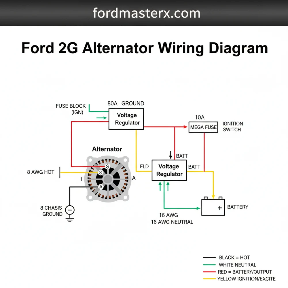
The Ford 2G alternator wiring diagram illustrates connections between the internal regulator and battery. A heavy hot wire links to the battery, while the regulator plug uses a common terminal for stator sensing and a traveler wire for the dashboard light. A solid ground wire is required to complete the high-current circuit.
📌 Key Takeaways
- The diagram maps the connections between the alternator, internal regulator, and vehicle battery.
- Identifying the large battery output terminal and the three-wire regulator plug is essential.
- Always disconnect the negative battery cable before touching wires to prevent electrical shorts.
- Pay close attention to the regulator plug, as these are prone to overheating and melting.
- Use this diagram for replacing the alternator or upgrading to a 3G unit for better safety.
If you are maintaining or restoring a classic Ford vehicle from the late eighties or early nineties, understanding the ford 2g alternator wiring diagram is essential for both vehicle performance and safety. The Second Generation (2G) alternator is a common sight in these engine bays, yet its unique dual-plug configuration often causes confusion for DIY mechanics. This guide provides a clear visual and technical breakdown of how the regulator and output plugs interact to charge your battery. By following this detailed wiring sequence, you will learn how to identify specific terminals, ensure proper grounding, and prevent common electrical failures associated with this specific charging system.
Technical Breakdown of the Ford 2G Alternator Components
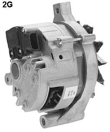
The Ford 2G alternator is distinguished by its integral voltage regulator and its specific two-plug interface. Unlike later 3G models that moved toward a more robust stud-style output, the 2G utilizes a high-amperage plastic connector that houses both the main charging leads and the stator signal. Understanding the ford 2g alternator wiring diagram requires a look at two distinct connection points: the regulator plug and the main power plug.
The regulator plug, often referred to as the “I-A-S” plug, contains three wires that control the charging logic. The “I” terminal (typically Green/Red) acts as the exciter or traveler wire, bringing signal voltage from the ignition switch to “turn on” the alternator. The “A” terminal (Yellow/White) is the battery sense wire, which monitors the actual voltage at the battery or starter solenoid. The “S” terminal (White/Black) is the stator wire, which loops directly into the second plug on the alternator to provide a tachometer-like signal to the regulator.
The second plug, which is the larger of the two, carries the primary electrical load. It typically consists of two heavy-gauge “hot wire” leads (Black/Orange) and the other end of the White/Black stator wire. Because the 2G design pushes significant current through these small spade terminals rather than a heavy-duty post, the diagram emphasizes the need for clean, tight connections. Proper identification of the ground wire path is also critical, as the alternator case itself often acts as the common terminal for the grounding circuit, sometimes assisted by a dedicated brass screw on the rear housing for additional ground bonding.
Visual Representation of Ford 2G Alternator Wiring: Showing the I-A-S Regulator Plug, the 3-Pin Power Plug, and the connection to the Starter Relay/Battery.
Step-by-Step Installation and Wiring Guide

Following a ford 2g alternator wiring diagram requires a methodical approach to ensure the electrical system remains stable under load. Before beginning, ensure you have a multimeter, high-quality wire strippers, and replacement connectors if your existing ones show signs of heat damage.
The Ford 2G alternator is limited in its output (usually 65-75 amps). If you add high-draw accessories like electric fans, ensure your wire gauge is sufficient to handle the heat generated at the plug interface.
Step 1: Identify the Regulator Pins
Locate the three-pin harness that connects to the side-mounted voltage regulator. The pins are labeled I, A, and S. The “A” wire (Yellow/White) should be connected to the “hot” side of the starter relay. This wire “senses” the battery voltage and tells the regulator when to increase output. The “I” wire (Green/Red) is your traveler wire that connects to the ignition switch, often through a dashboard charge lamp.
Step 2: Connect the Stator Loop
The “S” terminal on the regulator (White/Black) must be connected to the single thin wire on the main power plug. This is a feedback loop. This “neutral wire” equivalent in the DC system allows the regulator to monitor the internal operation of the alternator’s stator. Without this connection, the alternator will not charge correctly, or the dash light will stay illuminated.
Step 3: Wire the Main Power Output
The larger plug contains two thick wires, usually Black with an Orange stripe. These are the “hot wire” connections. In the standard ford 2g alternator wiring diagram, these two wires merge into a single large-gauge cable that runs to the starter solenoid or battery positive terminal. It is vital that these wires are protected by a fuse link (usually 14 or 16 gauge fuse link wire) to prevent a fire in the event of a short circuit.
Step 4: Establish a Solid Ground
While the alternator usually grounds through its mounting brackets to the engine block, a dedicated ground wire is highly recommended. Locate the brass screw or a designated ground bolt on the back of the alternator housing. Run a heavy-gauge wire from this point to the common terminal of the battery or a clean spot on the chassis. This ensures the voltage remains stable and reduces electrical noise.
Step 5: Verify Wire Gauge and Integrity
Check that the “hot wire” leads are at least 10-gauge or 8-gauge, depending on the length of the run. Using a wire gauge that is too thin will cause excessive resistance, leading to heat buildup at the plug. Ensure all connections are crimped tightly and protected with heat-shrink tubing.
Step 6: Final Voltage Testing
Once the wiring is complete and the battery is reconnected, start the engine. Use a multimeter to check the voltage at the battery terminals. A healthy 2G system should show between 13.8 and 14.4 volts. If the voltage remains at battery level (approx. 12.6V), re-check the Green/Red traveler wire for 12V signal when the key is in the “ON” position.
The 2G alternator is famous for its main plug catching fire. If the plastic around the three-pin power plug looks discolored, melted, or brittle, replace the harness pigtail immediately before attempting to use the vehicle.
Common Troubleshooting and Diagram Interpretation
When the charging system fails, the ford 2g alternator wiring diagram becomes your primary diagnostic map. The most frequent issue encountered with these units is a high-resistance connection at the primary output plug. Because this plug carries the full current of the alternator through two small pins, corrosion or loose fitment creates heat, which further increases resistance, eventually melting the plastic.
If your dashboard battery light is flickering, check the “I” terminal (Green/Red wire). This circuit must have continuity through the bulb for the alternator to “excite” and begin charging. If the bulb is blown, the traveler wire won’t send the necessary signal to the regulator. Another common failure is the “A” terminal sense wire. If this wire is broken or has a poor connection at the starter relay, the regulator will “think” the battery is dead and overcharge the system, potentially boiling the battery.
- ✓ Dim Headlights: Often caused by a poor ground wire connection or a failing “A” sense wire.
- ✓ Squealing Noises: Usually a belt tension issue, but can be an internal bearing failure.
- ✓ Burning Smell: Immediate sign of the main power plug overheating; inspect the Black/Orange wires.
- ✓ Zero Output: Check the White/Black neutral/stator wire for a secure loop between the two plugs.
Best Practices for Maintenance and Reliability
To ensure your charging system remains reliable, proactive maintenance of the wiring is just as important as the alternator itself. One of the best upgrades for a 2G-equipped vehicle is replacing the factory output harness with a new, heavy-duty pigtail. Modern replacement plugs often use superior heat-resistant plastics and better terminal tension to prevent the “melt-down” scenario common with original factory equipment.
Apply a small amount of dielectric grease to the plug terminals. This prevents moisture from entering the connection and protects against the corrosion that leads to high-resistance heat buildup.
Always ensure your battery terminals and the common terminal on the starter relay are free of oxidation. Use a wire brush to clean the brass screw grounding points on the alternator case. If you find yourself frequently replacing 2G alternators, consider a “3G Upgrade.” The 3G alternator uses a through-bolt for the main power output (hot wire), which eliminates the plug-melting issue entirely and provides much higher amperage at idle.
When following the ford 2g alternator wiring diagram for a repair, never bypass the fuse links. These are the “safety valves” of your electrical system. If a surge occurs or the alternator shorts internally, the fuse link will melt, saving the rest of your vehicle’s harness from total destruction. Lastly, ensure the belt is properly tensioned; a slipping belt will not only reduce voltage output but also create excessive heat that can damage the internal diodes of the regulator.
In conclusion, maintaining a proper ford 2g alternator wiring diagram and ensuring every traveler wire, hot wire, and ground wire is in top condition will keep your vintage Ford on the road. By understanding the I-A-S logic and the high-current demands of the power plug, you can enjoy a reliable electrical system for years to come.
Frequently Asked Questions
Where is the Ford 2G alternator located?
The Ford 2G alternator is located on the front of the engine, typically mounted to a bracket on the passenger or driver side. It is driven by the engine’s drive belt. You can find it by following the belt to the unit with a large external cooling fan.
What does the Ford 2G alternator wiring diagram show?
This diagram displays the electrical path from the alternator output to the battery, the ignition switch, and the charging indicator. It highlights the regulator connector pins, including the stator tap and battery sense wires, which are critical for maintaining the correct voltage level while the engine is running.
How many wires does a Ford 2G alternator have?
A Ford 2G alternator typically uses four main wires. The large output wire carries current to the battery. The small three-wire regulator plug contains the ‘I’ terminal for the indicator light, the ‘S’ terminal for stator sensing, and the ‘A’ terminal which connects back to the battery.
What are the symptoms of a bad Ford 2G alternator?
Common symptoms include a dimming dashboard, flickering headlights, or a dead battery after driving. A major warning sign for the 2G model is a burning plastic smell or visible charring on the wiring harness plug, which can lead to a fire if the connection becomes loose or corroded.
Can I replace a Ford 2G alternator myself?
Yes, replacing a Ford 2G alternator is a standard DIY project. It involves loosening the belt tensioner, removing the mounting bolts, and unplugging the harness. However, because the 2G plugs are prone to failure, many experts recommend replacing the wiring pigtail simultaneously to ensure a secure, fire-safe connection.
What tools do I need for this task?
To work on the Ford 2G alternator, you will need a basic socket set, a wrench for the battery terminals, and a multimeter for testing voltage. If you are replacing the connector, you will also need wire strippers, crimpers, and heat-shrink tubing to ensure a professional, moisture-resistant finish.