F250 Free Ford Wiring Diagrams: Easy Setup Guide
F250 free ford wiring diagrams provide a visual map of the truck’s electrical system, showing how the battery connects to various modules. These schematics illustrate the path from the power source through fuses and relays to the final component, ensuring you can identify every hot wire and ground wire accurately during repairs.
📌 Key Takeaways
- Map the truck’s complete electrical architecture efficiently
- Identify the central fuse box and relay locations quickly
- Always disconnect the battery before handling live circuits
- Use a multimeter to verify voltage at the common terminal
- Utilize these schematics for lighting upgrades or engine repairs
Finding reliable f250 free ford wiring diagrams can often feel like searching for a needle in a haystack, especially when you are dealing with complex electrical failures or installing high-draw aftermarket accessories. Whether you are troubleshooting a flickering headlight, a non-responsive power window, or a complicated trailer brake controller, having a precise visual map of your vehicle’s electrical system is non-negotiable. This article provides a deep dive into the architecture of Ford’s heavy-duty electrical systems, helping you decode wire colors, identify terminal locations, and master the sequence of connections required for a professional-grade repair. You will learn how to distinguish between different circuit types and how to use technical diagrams to pinpoint faults before they lead to costly component damage.
Most Ford F-250 electrical systems utilize a negative ground system where the vehicle chassis acts as the return path for the electrical current. Always verify the specific wire gauge before replacing any segment of the harness to prevent overheating.
Understanding the F-250 Electrical Architecture
The electrical system in a Ford F-250 is divided into several major subsystems, each governed by a central distribution point. When looking at f250 free ford wiring diagrams, the most prominent feature you will encounter is the Power Distribution Box (PDB), usually located in the engine compartment, and the Central Junction Box (CJB) located inside the cabin. These boxes house the fuses and relays that manage the voltage flow to everything from the fuel pump to the infotainment system.
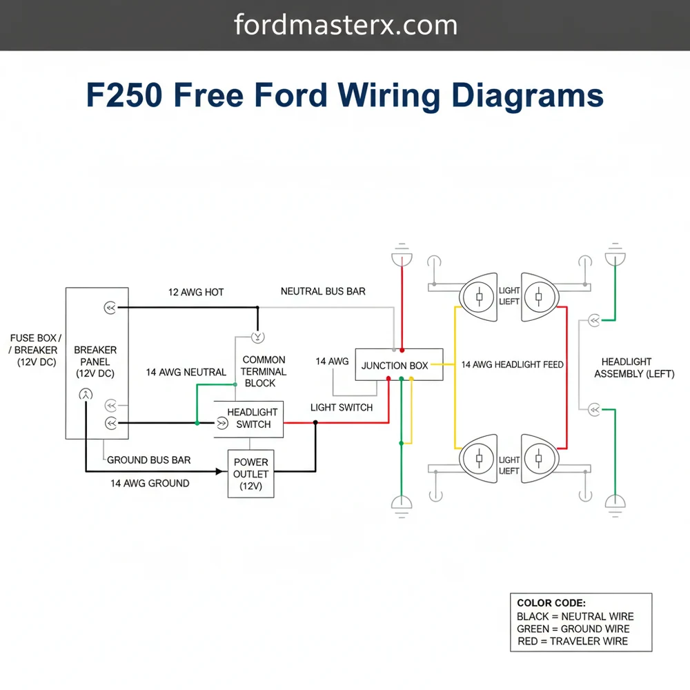
Each circuit in the diagram is labeled with a specific alphanumeric code that corresponds to its function. For instance, a hot wire—the wire carrying positive current from the battery—is often represented by solid red or yellow lines in the schematic. Conversely, the ground wire is typically black or green and connects directly to the vehicle’s frame. In specialized accessory wiring, such as a three-way lighting setup for a truck bed or a canopy, you may encounter a traveler wire. This wire facilitates communication between two different switches, allowing you to control a single light source from multiple locations.
The diagrams also highlight the common terminal, which serves as the primary connection point for multi-functional relays. In automotive relays, the common terminal (often labeled as Pin 30) receives the high-amperage power that is then switched to the output pins. Understanding the pinout of these terminals is critical because reversing the connections can lead to a short circuit or “fried” control modules. While automotive systems do not use a neutral wire in the same sense as residential AC wiring, the “return” path to the battery negative post serves a synonymous purpose in completing the loop.
How to Read and Execute the Wiring Sequence
Interpreting a complex wiring schematic requires a systematic approach. Follow these steps to ensure you are reading the diagram correctly and making safe, reliable connections.
- ✓ Step 1: Identify the Component and Circuit – Locate the specific part you are working on (e.g., the starter motor or the trailer plug) on the diagram. Look for the circuit number adjacent to the lines to ensure you are following the correct path through the various connectors.
- ✓ Step 2: Map the Power Source – Trace the hot wire back to its origin. This will usually lead you to a fuse in the PDB or CJB. Verify that the fuse is the correct amperage for the circuit’s voltage requirements and the wire’s gauge.
- ✓ Step 3: Locate Connection Points – Identify every connector (labeled as ‘C’ followed by a number, like C102) between the power source and the component. These are the most common sites for corrosion or loose pins.
- ✓ Step 4: Verify Ground Integrity – Follow the ground wire from the component to its termination point on the chassis. Automotive electrical issues are frequently caused by a “floating ground,” where the connection to the metal frame is rusted or loose.
- ✓ Step 5: Check for Switching Logic – If the circuit involves a switch or relay, identify the common terminal and the traveler wire paths. This is essential for accessories like auxiliary fog lights or winches where multiple trigger points might be used.
- ✓ Step 6: Match Wire Gauge to Load – Ensure that any replacement wire you install matches the gauge specified in the diagram. A wire that is too thin will create resistance, causing the voltage to drop and potentially starting a fire.
- ✓ Step 7: Physical Connection – When connecting to heavy-duty terminals, such as those on a winch or high-output alternator, ensure the ring terminal is seated firmly against the brass screw or copper stud. These materials provide the best conductivity and resist the high heat generated by heavy loads.
Never probe a wire with a sharp tester without resealing the insulation afterward. Moisture can enter the tiny hole, leading to internal wire corrosion (known as “green rot”) that can destroy an entire harness over time.
To perform these steps effectively, you will need a digital multimeter, a 12V test light, wire strippers, and a high-quality crimping tool. Always disconnect the negative battery terminal before cutting or splicing into the main harness to avoid accidental shorts that could deploy airbags or damage the Powertrain Control Module (PCM).
Troubleshooting Common F-250 Electrical Failures

The primary benefit of utilizing f250 free ford wiring diagrams is the ability to troubleshoot logically rather than guessing. One of the most frequent issues encountered in these trucks is a parasitic draw, where a component continues to pull voltage even when the ignition is off. By using the diagram, you can identify which circuits remain “always hot” and test them individually at the fuse box.
Another common problem is intermittent power loss to the trailer lights. In this scenario, you should look at the 7-pin connector diagram. Often, the common terminal for the trailer ground is corroded. If the trailer has internal battery charging, the hot wire (typically a 10-gauge or 12-gauge wire) must show a steady 13.5V to 14.4V when the truck is running. If the voltage is lower, use the diagram to trace the wire back to the charging relay under the hood.
If you find a melted fuse but the fuse didn’t actually “blow,” this indicates a “high-resistance” short or a loose terminal fit. Check the brass screw connections or the fuse tangs for signs of pitting or heat discoloration.
If you encounter a circuit where the lights are dim, it is usually a sign of excessive resistance. This can occur on the neutral wire or ground side just as easily as the power side. Use your multimeter to check for voltage drop by measuring the difference between the battery positive and the component positive while the circuit is under load. A drop of more than 0.5 volts usually indicates a problem with a connector or an undersized wire gauge.
Best Practices for Long-Term Electrical Reliability
Maintaining the integrity of your F-250’s wiring ensures the truck remains reliable for work and travel. When performing any repairs found via f250 free ford wiring diagrams, always use marine-grade heat shrink tubing for all splices. This prevents road salt and moisture from wicking into the copper strands.
Furthermore, pay close attention to how wires are routed. Avoid running a hot wire near sharp metal edges or high-heat areas like the exhaust manifold. Use plastic looms and secure them with zip ties to prevent vibration-induced chafing. If you are adding high-power accessories like a plow or a large winch, consider installing a dedicated secondary fuse block. This keeps the factory wiring pristine and makes future troubleshooting much simpler.
When making connections to the battery or high-current junction blocks, ensure the surfaces are clean. A small amount of dielectric grease can be applied to connectors to prevent oxidation, but do not use it on the actual contact faces of a brass screw terminal, as it can occasionally act as an insulator if applied too heavily. Instead, tighten the connection first, then coat the exterior to seal out the elements.
Finally, always document your changes. If you add a new traveler wire for a custom light bar or change the gauge of a charging circuit, note it down and keep a copy with your vehicle’s manual. This saves immense time for you or the next owner when using f250 free ford wiring diagrams in the future. By following these professional standards, you ensure that your Ford truck’s electrical system remains as robust as its chassis.
Step-by-Step Guide to Understanding the F250 Free Ford Wiring Diagrams: Easy Setup Guide
Identify – Start by identifying the specific circuit you need to troubleshoot within the f250 free ford wiring diagrams.
Locate – Locate the power source or hot wire feeding the component to check for proper battery voltage.
Understand – Understand how the ground wire completes the circuit to ensure proper current flow back to the chassis.
Connect – Connect your multimeter to the common terminal to measure resistance and continuity accurately across the electrical path.
Verify – Verify that any switching components, such as a traveler wire in auxiliary lighting, are functioning as intended.
Complete – Complete the inspection by ensuring the neutral wire equivalent or return path is free from corrosion or damage.
Frequently Asked Questions
Where is the fuse box located?
F250 fuse boxes are typically located in the engine compartment and under the dashboard on the driver’s side. Consult your owner’s manual or f250 free ford wiring diagrams to find specific fuse ratings for your year and model to avoid overloading any circuit or hot wire during a repair.
What do f250 free ford wiring diagrams show?
These diagrams show the complete path of electrical current through your truck’s systems. They illustrate how power travels from the battery, through fuses, switches, and relays, eventually reaching the ground wire to complete the circuit. They are essential for identifying wire colors and specific pin locations for troubleshooting.
How many wires does the ignition switch have?
Most F250 ignition switches utilize five to seven main wires depending on the production year. This includes a primary hot wire for battery power, an accessory lead, and various start/run wires. Use a wiring diagram to identify which wire connects to the common terminal for consistent power delivery to the starter.
What are the symptoms of a bad ground wire?
Symptoms of a bad ground wire include flickering lights, intermittent power loss, and erratic sensor readings. If the ground connection is loose or corroded, electrical current cannot return to the battery effectively, causing components to malfunction or fail completely during high-load operations or bumpy driving conditions on the road.
Can I diagnose electrical faults myself?
Yes, you can diagnose many electrical issues using f250 free ford wiring diagrams and basic tools. By tracing the hot wire and testing for continuity, most DIYers can identify broken wires or blown fuses. However, complex computer module issues may require professional diagnostic equipment for a full resolution.
What tools do I need for testing circuits?
To test your F250’s electrical system, you will need a digital multimeter, a test light, and wire strippers. These tools allow you to check voltage at the common terminal, verify grounding, and ensure that every hot wire and traveler wire in your specialized lighting system is conducting electricity properly.