Engine Triton Ford 5.4 Vacuum Hose Diagram: Step-by-Step
The engine triton ford 5.4 vacuum hose diagram maps connections between the intake manifold, PCV valve, brake booster, and EVAP system. This system provides necessary vacuum to components monitored by the ECU. Properly routed lines prevent lean air-fuel conditions, ensuring the OBD-II system does not trigger a diagnostic code during operation.
📌 Key Takeaways
- Illustrates all vacuum supply and return lines for the 5.4L Triton V8.
- Primary ports serve the brake booster, PCV valve, and EVAP purge solenoid.
- Vacuum leaks are a leading cause of P0171 and P0174 lean codes.
- The rubber elbow at the back of the intake is the most common failure point.
- A secure vacuum system is vital for smooth idling and power brake assist.
Navigating the complexities of a Ford 5.4L Triton V8 engine requires more than just basic mechanical knowledge; it demands precision, especially when dealing with the intricate vacuum system. Whether you are battling a rough idle, poor fuel economy, or a stubborn lean code, having an accurate engine triton ford 5.4 vacuum hose diagram is the most critical tool in your arsenal. This specific engine family, found in millions of F-Series trucks and Expeditions, relies heavily on vacuum pressure to manage everything from emissions and braking to four-wheel-drive engagement. In this guide, you will learn how to identify every major vacuum circuit, interpret the routing schematics, and use diagnostic tools to restore your engine’s performance.
The Ford 5.4L Triton vacuum system is a sophisticated network of rubber hoses, plastic lines, and electronically controlled solenoids that communicate directly with the ECU. Understanding the diagram begins with identifying the primary vacuum source: the intake manifold. From this central hub, vacuum pressure is distributed to several critical subsystems. On a standard 3-valve or 2-valve Triton engine, the diagram typically highlights the PCV (Positive Crankcase Ventilation) system, which routes crankcase gases back into the intake to be burned. Another major component is the EVAP (Evaporative Emission) system, which includes the vapor canister purge valve usually mounted on the driver’s side firewall or intake.
For owners of 4WD models, the engine triton ford 5.4 vacuum hose diagram also includes the Integrated Wheel End (IWE) system. This system uses vacuum to disengage the front hubs; when vacuum is lost, the hubs default to a locked position. The diagram also tracks the lines going to the Brake Booster, ensuring power-assisted braking, and the Intake Manifold Runner Control (IMRC) solenoids, which adjust airflow for better low-end torque. You will often see color-coding in these diagrams: red or black lines often denote high-vacuum supply lines, while green or blue lines frequently represent lines leading to the EVAP service ports or fuel pressure regulators.
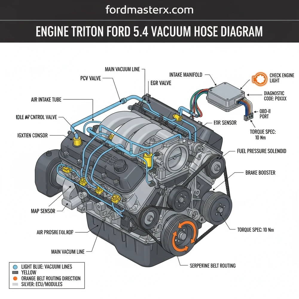
[DIAGRAM_PLACEHOLDER: A detailed technical schematic showing the Ford 5.4L Triton intake manifold with labeled lines for the PCV Valve, Brake Booster, IWE Solenoid, EVAP Purge Valve, and Fuel Pressure Sensor. Lines are color-coded to show vacuum flow from the rear of the intake to the various engine bay components.]
On many 5.4L Triton engines, the most common source of a vacuum leak is the rubber “elbow” connector located at the very back of the intake manifold. This part is notorious for dry-rotting and collapsing, leading to immediate lean codes and engine stumbling.
Interpreting a vacuum diagram and applying it to your engine bay is a systematic process. Follow these steps to ensure you are tracing and installing lines correctly:
- ✓ Step 1: Locate the VECI Label. Before looking at aftermarket diagrams, check under the hood for the Vehicle Emission Control Information (VECI) sticker. This is the factory-authorized diagram specific to your VIN and calibration.
- ✓ Step 2: Connect the OBD-II Scanner. If your check engine light is on, use an OBD-II tool to pull a diagnostic code. Codes P0171 and P0174 (System Too Lean) are the “smoking guns” for a vacuum leak.
- ✓ Step 3: Identify the Main Vacuum Tree. Locate where the lines exit the intake manifold. On the 5.4 Triton, this is usually behind the throttle body or at the rear of the plenum near the firewall.
- ✓ Step 4: Trace the PCV Circuit. Follow the thickest hose from the passenger side valve cover to the intake manifold. Ensure the PCV valve is seated tightly and the hose has no soft spots.
- ✓ Step 5: Inspect the IWE Solenoid (4WD Models). Locate the solenoid on the firewall. Use the diagram to confirm which line goes to the vacuum reservoir and which goes down to the wheel hubs.
- ✓ Step 6: Test with a Smoke Machine. If a visual inspection fails, inject diagnostic smoke into the vacuum system. Watch for smoke escaping from brittle plastic lines or hidden gaskets.
- ✓ Step 7: Verify ECU Solenoids. Ensure the electrical connectors to the EVAP and IMRC solenoids are secure, as the ECU uses these to pulse vacuum flow during specific driving conditions.
When performing this work, you will need a basic set of hand tools, including needle-nose pliers for hose clamps, a vacuum gauge for testing pressure levels, and a mirror to see the connections at the back of the engine. Always ensure the engine is cool before reaching behind the intake manifold, as the proximity to the EGR pipe can cause burns.
Do not attempt to “guess” vacuum routing. Crossing an EVAP line with a PCV line can cause excessive pressure in the fuel tank or oil leaks in the engine seals. Always refer back to the engine triton ford 5.4 vacuum hose diagram for your specific model year.
The 5.4 Triton is susceptible to several specific vacuum-related failures. The most common symptom is a “hissing” sound coming from the engine bay while idling. Because vacuum is highest at idle, leaks are most apparent when the vehicle is stopped. If you experience a hard brake pedal, the vacuum line to the brake booster or the booster diaphragm itself has likely failed. If your 4WD makes a grinding noise while driving in 2WD, the vacuum hubs are likely partially engaging due to a leak in the IWE lines.
Using the diagnostic code from your OBD-II scanner can narrow down the search. If you see P0401, it relates to the EGR system, which is vacuum-operated on many 5.4 variants. A P0442 or P0455 indicates a leak in the EVAP circuit. By looking at the diagram, you can isolate these specific sections of the engine rather than inspecting every single hose. If your engine has a “ticking” sound that disappears when you pull a vacuum line, you might be confusing a vacuum leak with a mechanical issue like a timing chain rattle or a loose spark plug, which are also common on the Triton platform.
When replacing old vacuum lines, use high-quality silicone hoses instead of standard rubber. Silicone resists the high under-hood heat of the 5.4L V8 much better and won’t become brittle over time, preventing future diagnostic codes.
Maintaining the vacuum system on your Ford 5.4 is part of a broader health strategy for the engine. For instance, when you are replacing the accessory belt or water pump, take a moment to inspect the vacuum lines that run near the front of the engine, as they can be nicked or moved during other repairs. If you ever have to remove the intake manifold to address a coolant flow issue or replace a knock sensor, always use the correct torque spec for the intake bolts. Over-tightening can crack the plastic manifold, creating a permanent vacuum leak that no diagram can fix.
Furthermore, keep an eye on the timing chain guides; if they wear down, the resulting debris can occasionally clog the oil passages that affect the VCT (Variable Cam Timing) solenoids. While this is an oil pressure issue, it often mimics the symptoms of a vacuum leak by causing a rough idle. By staying proactive and using a high-quality engine triton ford 5.4 vacuum hose diagram, you can ensure your truck remains reliable for years to come. Investing in a small handheld vacuum pump is a cost-saving move that allows you to test individual components like the EGR valve or IWE actuators without replacing expensive parts unnecessarily.
In conclusion, mastering the engine triton ford 5.4 vacuum hose diagram is essential for any DIYer or professional working on these legendary Ford powerplants. By understanding how the ECU monitors these systems and knowing where the common failure points lie—such as the rear intake elbow and the EVAP solenoids—you can quickly clear that check engine light and restore your vehicle’s drivability. Proper diagnosis through the diagram saves time, reduces frustration, and keeps your Triton V8 running at peak efficiency.
Frequently Asked Questions
Where is the PCV valve located?
On the Ford 5.4 Triton engine, the PCV valve is located on the passenger-side valve cover. It connects to the rear of the intake manifold via a thick rubber hose. This line is a frequent source of vacuum leaks that trigger a check engine light and rough idle.
What does the vacuum hose diagram show?
The engine triton ford 5.4 vacuum hose diagram provides a visual layout of the vacuum circuit, including the intake manifold source, the brake booster, and the fuel pressure regulator. It helps mechanics trace lines back to the ECU sensors to ensure correct air-to-fuel ratio management.
How many vacuum connections does the manifold have?
The 5.4 Triton manifold typically has four to six primary vacuum connections. These include the main brake booster line, the PCV intake port, the EVAP purge line, and smaller connections for the 4WD solenoid and the HVAC vacuum reservoir under the dash area.
What are the symptoms of a bad vacuum hose?
Common symptoms include a high or erratic idle, decreased braking performance, and a ‘hissing’ sound. When a hose fails, the OBD-II system will likely register a diagnostic code such as P0171, indicating the engine is running lean due to unmetered air entering the system.
Can I replace these vacuum hoses myself?
Yes, replacing these hoses is a standard DIY task. Most lines use simple friction-fit connectors or small spring clamps. It is best to refer to the engine triton ford 5.4 vacuum hose diagram and replace hoses one at a time to ensure they are connected to the correct ports.
What tools do I need for this task?
You will need needle-nose pliers for hose clamps, a flashlight, and a basic socket set if removing the intake manifold. Use an OBD-II scanner to clear codes. If removing the manifold, you must use a torque wrench to ensure the bolts meet the manufacturer’s specific torque spec.


