Edelbrock Electric Choke Wiring Diagram: Easy Setup Guide
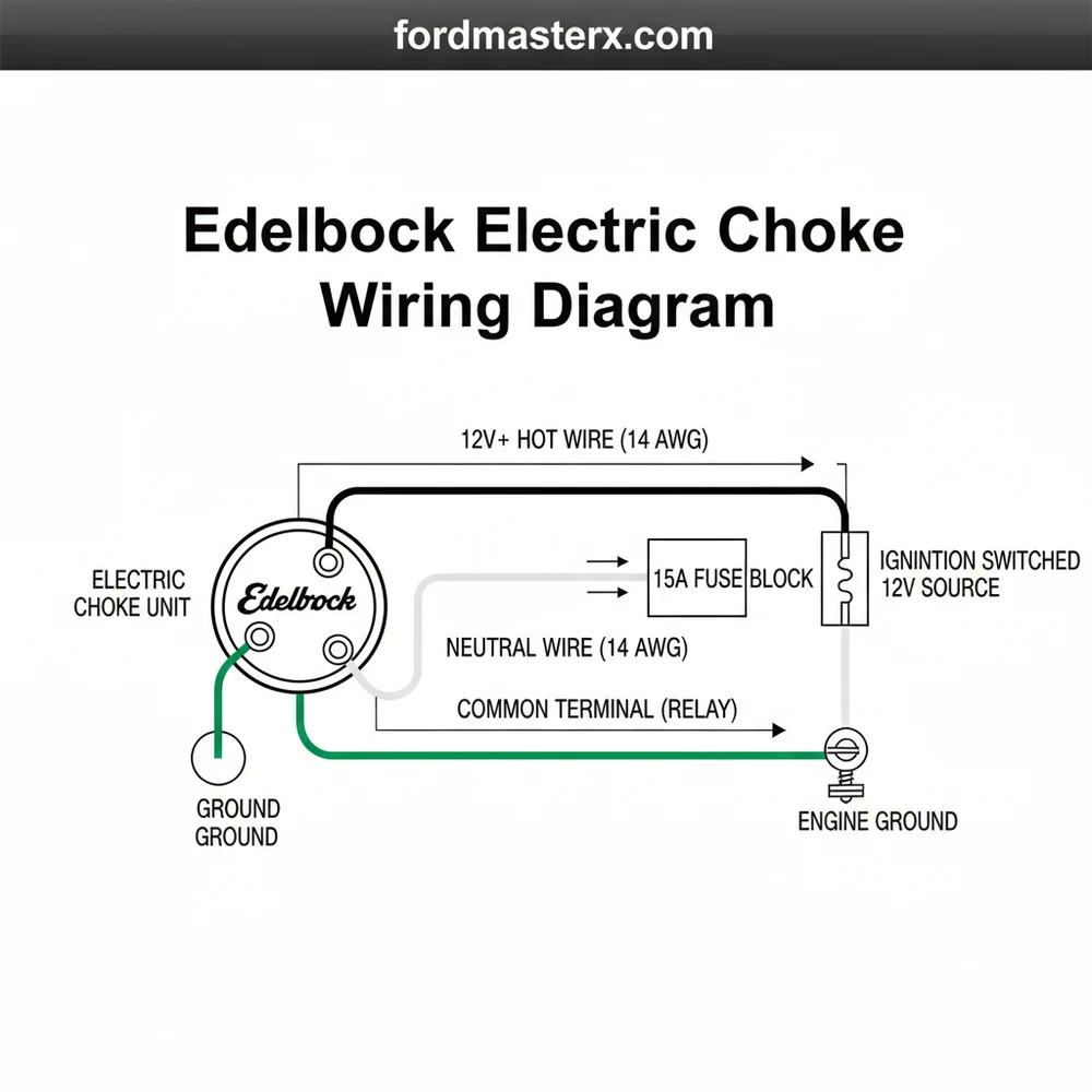
An Edelbrock electric choke wiring diagram illustrates connecting the choke’s positive terminal to a 12V hot wire that is only active when the ignition is on. Unlike a 120V system with a neutral wire or traveler wire, this DC setup uses a ground wire attached to a common terminal on the carburetor body.
📌 Key Takeaways
- Explains the electrical path for automatic choke operation
- Identify the choke cap and its positive/negative terminals
- Never connect the choke to the ignition coil’s positive side
- Use a fused 12V source that only receives power when the key is on
- Use this diagram when installing a new carb or fixing cold start issues
Installing an Edelbrock carburetor is one of the most popular upgrades for classic car enthusiasts looking to improve reliability and performance. However, once the carburetor is bolted to the intake manifold, many DIYers find themselves staring at the electric choke mechanism, wondering exactly how to wire it for optimal operation. The electric choke is a critical component that manages the air-fuel ratio during cold starts, ensuring your engine fires up smoothly and idles correctly until it reaches operating temperature. Understanding the Edelbrock electric choke wiring diagram and the logic behind the circuit is essential for preventing common issues like battery drain, fouled spark plugs, or hard-starting conditions in cold weather.
Main Components and Features
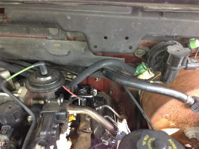
Before diving into the wiring process, it is important to identify the specific components that make up the Edelbrock electric choke system. Most Edelbrock Performer Series (1406, 1407, etc.) and AVS2 carburetors utilize a very similar choke design. The system relies on a bimetallic coil housed inside a black plastic cap on the passenger side of the carburetor.
The primary components include:
- The Choke Cap: This is the black circular housing. Inside is a bimetallic spring that expands when heated. As it expands, it rotates the choke shaft to open the butterfly valve at the top of the carburetor.
- Positive (+) Terminal: Located on the side of the choke cap, this is usually a male spade connector. It requires a 12-volt “switched” power source.
- Negative (-) Terminal/Ground: Most Edelbrock chokes feature a second spade terminal for a ground wire. On some older models, the choke may ground through the carburetor body itself, but using a dedicated ground wire to a clean engine ground or the intake manifold is the modern standard for reliability.
- Fast Idle Cam: While not electrical, this mechanical linkage works in tandem with the choke. It holds the throttle open slightly during the warm-up phase.
- Adjustment Screws: There are three small screws holding the black cap in place. Loosening these allows you to rotate the cap to adjust how much “tension” is on the choke plate when the engine is cold.
How to Read and Implement the Wiring Diagram

The wiring diagram for an Edelbrock electric choke is relatively simple, but the “source” of the power is where most mistakes are made. The goal is to provide a steady 12-volt DC signal to the choke only when the engine is running or the ignition key is in the “ON” position.
The Positive (+) Connection
The red (or positive) wire must be connected to a switched 12V source. This means the wire should only have power when the ignition key is turned to the “Run” position. You should never connect the choke directly to the battery, as this will keep the heating element on 24/7, eventually burning out the coil and draining your battery overnight.
Common locations to tap for 12V switched power include:
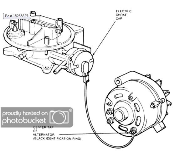
- The Fuse Box: Look for a terminal marked “IGN” or “ACC.” This is the safest and cleanest method.
- Wiper Motor Power: On many GM vehicles, the wiper motor receives a switched 12V feed that is easily accessible in the engine bay.
- Electric Cooling Fan Relay: If you have an aftermarket fan controller, you can often tap into the trigger wire.
The Negative (-) Connection
The black (or negative) wire connects the choke to the vehicle’s ground. While the carburetor is bolted to the engine, the gaskets and various coatings can sometimes act as insulators. For a guaranteed circuit, run a short 14-gauge wire from the negative spade terminal on the choke cap to a clean, unpainted bolt on the intake manifold or the cylinder head. Ensure you use a ring terminal for a secure connection.
Installation Steps for DIYers
Follow these steps to ensure your wiring is professional and durable:
- Disconnect the Battery: Before performing any electrical work, disconnect the negative battery cable to prevent accidental shorts.
- Prepare the Wires: Cut your 14-gauge wire to length. Use a wire stripper to remove about 1/4 inch of insulation from each end.
- Crimp the Terminals: Use high-quality female spade connectors for the choke end and the appropriate connector (ring or fuse tap) for the power source end. Use a professional crimping tool rather than pliers to ensure the wire doesn’t vibrate loose.
- Route the Wiring: Run the wires along the existing engine harness. Avoid placing wires near high-heat sources like exhaust headers or moving parts like the throttle linkage or fan blades. Use plastic wire loom and zip ties to keep the installation neat.
- Secure the Connections: Plug the positive wire into the terminal marked with a (+) and the ground wire into the terminal marked with a (-).
- Test the Circuit: Reconnect the battery. Turn the key to the “ON” position (do not start the engine). Use a multimeter or a test light to verify that 12V is reaching the positive terminal.
Tips for Optimal Performance
Once wired, the electric choke requires a bit of fine-tuning to match your local climate and engine’s needs. Here are several tips to get the most out of your setup:
- The “Index Mark” Adjustment: On the black choke cap and the metal housing, you will see small notched lines. These are index marks. Typically, setting the cap so the middle mark aligns with the housing mark is the “factory” setting. In colder climates, you may need to rotate the cap slightly counter-clockwise (to tighten the spring) to keep the choke closed longer.
- Fast Idle Setting: The electric choke controls the fast idle cam. Once the engine is started, you may need to adjust the fast idle screw (located behind the choke housing) to set the cold-start RPM. Usually, 1,200 to 1,500 RPM is ideal for a cold engine.
- Check for Smooth Movement: Before starting the car, manually move the throttle linkage to ensure the choke butterfly snaps shut freely. If it sticks, check for dirt or binding in the linkage.
- Use Heat Shrink: For a truly professional DIY job, use marine-grade heat shrink tubing over your crimp connectors. This prevents moisture from corroding the copper wire inside the terminals, which is a common cause of choke failure over time.
Troubleshooting Common Issues
If your Edelbrock electric choke isn’t behaving as expected, use this troubleshooting guide to identify the culprit:
The Choke Never Opens
If the choke plate stays closed even after the engine is hot, the heating element is not getting power. First, check your fuse. If the fuse is intact, use a multimeter to check for 12V at the positive terminal with the key on. If power is present, check the ground. If both power and ground are verified, the internal bimetallic coil may be broken, and the choke cap will need replacement.
The Choke Opens Too Fast
If the engine stumbles and dies shortly after starting because the choke opened too quickly, the cap may be set too “lean.” Loosen the three retaining screws and rotate the cap toward the “Rich” direction (usually marked on the cap). This puts more tension on the spring, requiring more heat before the choke opens.
The Engine Won’t Return to Normal Idle
This is often a mechanical issue rather than an electrical one. The fast idle cam may be sticking. After the engine is warm and the choke plate is fully vertical (open), tap the throttle. The linkage should drop off the fast idle cam. If it doesn’t, clean the linkage with carburetor cleaner and ensure no wires are obstructing the movement.
Battery Drains Overnight
This is a classic symptom of wiring the choke to a “constant” 12V source rather than a “switched” source. Use a test light with the ignition key removed. If the light glows when touching the choke’s positive terminal, you have wired it to a constant power source and must move the wire to a switched terminal in the fuse box.
By following this guide and adhering to the wiring diagram principles, you can ensure your Edelbrock carburetor provides reliable, “turn-key” starts in any weather. Proper wiring not only improves the drivability of your classic vehicle but also protects your electrical system and engine longevity.
Step-by-Step Guide to Understanding the Edelbrock Electric Choke Wiring Diagram: Easy Setup Guide
Identify the positive and negative terminals on the black choke cap.
Locate a 12V switched hot wire source that only has power when the ignition is ON.
Understand how to route the ground wire to a clean common terminal or bolt on the intake manifold.
Connect the positive lead from the switched source to the plus terminal on the choke.
Verify that the choke plate begins to open slowly when the ignition key is turned.
Complete the installation by securing all wires away from moving linkage and high-heat areas.
Frequently Asked Questions
Where is the electric choke located?
The electric choke is located on the passenger side of the Edelbrock carburetor, housed within a round black plastic cap. It is mounted near the secondary throttle linkage and is easily identifiable by the two metal spade terminals protruding from its side for electrical connections.
What does an Edelbrock electric choke wiring diagram show?
The diagram shows the flow of current from a 12-volt switched ignition source to the choke heating element. It illustrates how the hot wire provides power to warm the internal spring, while the ground wire completes the circuit to the chassis, ensuring the choke plate opens as the engine warms.
How many wires does an Edelbrock electric choke have?
The Edelbrock electric choke uses two primary connections: one positive and one negative. While the negative side usually uses a short ground wire to a common terminal on the carburetor, the positive side requires a 12V hot wire. Unlike home AC circuits, it does not use a neutral wire.
What are the symptoms of a bad electric choke?
A failing choke often causes difficult cold starts or high idling once the engine is warm. If the wiring is faulty or the heating element burns out, the choke plate will remain closed, leading to a rich fuel mixture, black exhaust smoke, and poor fuel economy during operation.
Can I install this wiring myself?
Yes, installing Edelbrock electric choke wiring is a straightforward DIY task for most vehicle owners. It requires basic electrical knowledge to find a switched 12V source. Ensuring a solid ground and using proper connectors prevents voltage drops that could hinder the choke’s ability to open fully.
What tools do I need for this wiring task?
You will need a digital multimeter to identify a switched 12V power source, wire strippers, and a crimping tool for terminal connectors. Additionally, a set of screwdrivers is necessary to adjust the choke cap’s tension once the electrical connections are successfully completed and tested.