Edelbrock 1406 Throttle Linkage Diagram: Setup Guide
An Edelbrock 1406 throttle linkage diagram illustrates the connections between the throttle cable, return springs, and transmission kickdown. To set it up, align the cable bracket, attach the throttle stud to the primary lever, and ensure the return springs are under tension. Proper alignment prevents sticking and ensures smooth pedal travel.
📌 Key Takeaways
- Visualizes the correct cable, spring, and kickdown placement
- The throttle lever arm and stud are the most critical identification points
- Always ensure the throttle does not stick in the wide-open position
- Using Edelbrock-specific brackets ensures the best geometry and fitment
- Essential for carburetor swaps or resolving throttle response issues
When you are upgrading your engine or refurbishing a classic vehicle, few components are as vital to the driving experience as the carburetor. Setting up your edelbrock 1406 throttle linkage diagram correctly is the difference between a smooth, responsive ride and a frustrating day in the garage. This guide provides a detailed look at how the throttle linkage interacts with your 600 CFM Performer Series carburetor. You will learn to identify every pivot point, spring attachment, and bracket location to ensure your mechanical connection is flawless from the pedal to the butterflies.
The Edelbrock 1406 is designed for fuel economy and performance. Unlike modern fuel injection systems managed by an ECU, this carburetor relies entirely on mechanical geometry to deliver the correct air-fuel mixture. Precision in your linkage setup is mandatory for safety and performance.
Understanding the Edelbrock 1406 Throttle Linkage Components
The throttle linkage on an Edelbrock 1406 is a multifaceted assembly located on the driver’s side of the carburetor body. To read the diagram effectively, you must first identify the primary throttle lever. This is the large, vertical metal plate attached to the primary throttle shaft. It features several holes of varying sizes. The largest hole at the top is typically reserved for the main throttle cable or rod coming from your firewall.
Beneath the main attachment point, you will find smaller holes designed for the throttle return springs. These are critical for safety, ensuring the butterflies snap shut when you lift your foot. Further down the lever, there are specific attachment points for transmission kickdown cables. If you are running an automatic transmission like a TH350 or a 700R4, the geometry of this connection dictates when your transmission downshifts under load.
The diagram also highlights the fast idle cam and the electric choke linkage. These components are interconnected; when the choke is closed, the linkage holds the throttle open slightly to keep the engine running while it warms up. Properly identifying the relationship between the choke rod and the throttle lever is essential for cold-start reliability. Unlike modern vehicles where a diagnostic code would identify a sensor failure, a manual inspection of these physical parts is your primary way to ensure the engine idles down correctly as it reaches operating temperature.
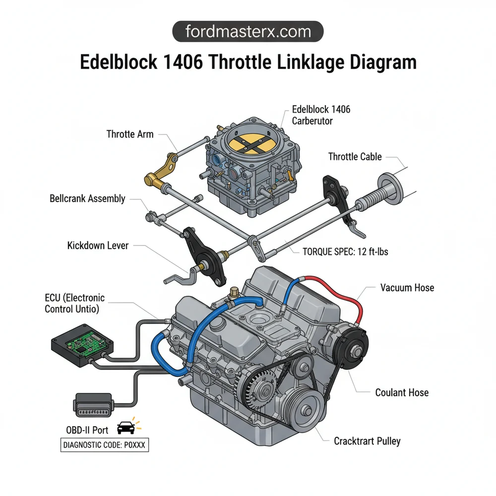
[DIAGRAM_PLACEHOLDER – A detailed technical illustration showing the driver-side view of an Edelbrock 1406 carburetor. Labels point to: 1. Main Throttle Stud, 2. Transmission Kickdown Hole, 3. Return Spring Anchor, 4. Cruise Control Attachment, 5. Fast Idle Adjustment Screw, 6. Choke Linkage Rod.]
Never operate your vehicle with a single throttle return spring. Always use a dual-spring setup. If one spring fails or breaks, the second spring provides the necessary tension to close the throttle and prevent a runaway engine scenario.
Step-by-Step Installation and Adjustment Guide

Correctly interpreting the edelbrock 1406 throttle linkage diagram is the first step toward a successful installation. Follow these steps to ensure your mechanical setup is synchronized and safe.
1. Mount the Carburetor and Bracket: Begin by securing the 1406 to your intake manifold. Ensure you use the correct gaskets to prevent vacuum leaks. Once the carburetor is seated, install your throttle cable bracket to the rear driver-side intake bolt. While you are here, verify that your coolant flow is unobstructed, as many intakes rely on coolant passages to regulate manifold temperature.
2. Identify Your Cable Type: Determine if your vehicle uses a hard rod or a braided cable. For most GM applications, you will need a throttle cable stud (Edelbrock part #8009 or similar) to provide a pivot point for the cable eyelet.
3. Attach the Main Linkage: Slide the throttle cable onto the uppermost large hole of the throttle lever. Secure it with a cotter pin or the provided nut. Ensure there is no binding. If you are using an automatic transmission, this is the time to install the specific adapter (such as a Mopar or Ford kickdown extension) as shown in the diagram.
4. Install Return Springs: Hook your dual return springs into the designated lower hole on the lever and stretch them back to the anchor point on your cable bracket. The tension should be firm but not so stiff that it causes leg fatigue during driving.
5. Verify Full Throttle Range: Have an assistant sit in the driver’s seat and slowly depress the gas pedal (with the engine off). Watch the linkage to ensure the primary and secondary butterflies open fully. At the same time, ensure the linkage does not strike the accessory belt or any nearby wiring.
6. Check for “Over-Center” Binding: Ensure that at full throttle, the linkage does not “lock” into an open position. The geometry must allow the springs to pull the lever back effortlessly.
7. Set the Fast Idle: Referencing your diagram, locate the fast idle screw behind the throttle lever. Adjust this so that when the choke is fully closed, the engine stays at approximately 1500 RPM.
8. Final Torque Check: Use a wrench to ensure the mounting nuts meet the recommended torque spec (usually 60-80 inch-pounds). Over-tightening can warp the carburetor base, leading to air leaks.
If your throttle feels “notchy” or sticks, check the alignment of the cable bracket. The cable should exit the housing in a perfectly straight line toward the throttle lever. Any angle in the cable will cause the inner wire to saw against the housing, creating friction.
Common Issues and Troubleshooting

Even with a perfect edelbrock 1406 throttle linkage diagram, mechanical issues can arise. One of the most common problems is a high idle that won’t drop down. This is often caused by the throttle linkage binding against the mounting studs or the air cleaner base. If the air cleaner is too large, it may physically prevent the lever from returning to the idle position.
Another frequent issue is improper transmission shifting. If your kickdown cable is too loose, the car will shift into top gear too early, making the engine feel sluggish. If it is too tight, it may refuse to upshift. Refer to your diagram to ensure you haven’t swapped the throttle cable hole with the kickdown cable hole.
In modern vehicles, you would look for a check engine light or use an OBD-II scanner to find a diagnostic code for these issues. On a carbureted engine, you must be the “computer.” Check for mechanical interference with the timing chain cover or the accessory belt drive if you have custom brackets. If you experience a “stumble” upon acceleration, check the accelerator pump linkage—the small rod that connects the top of the throttle lever to the pump plunger.
- ✓ Sticky Throttle: Check for burrs on the throttle shaft or interference with the gasket.
- ✓ Weak Return: Inspect springs for stretching or loss of tension; replace immediately.
- ✓ Incomplete Throttle Opening: Adjust the cable length at the firewall or bracket.
- ✓ Fast Idle Failure: Ensure the choke thermostat is receiving 12V power when the ignition is on.
Tips and Best Practices for Long-Term Reliability
To keep your Edelbrock 1406 performing at its peak, maintenance of the linkage is just as important as the internal tuning. Periodically apply a drop of light machine oil to the pivot points on the throttle lever. Avoid using heavy grease, as it tends to attract road grit and dirt, which can act as an abrasive and wear down the metal parts.
When performing other engine work, such as replacing a timing chain or adjusting an accessory belt, always re-verify your throttle clearance. It is surprisingly easy to accidentally nudge a bracket or move a wire into the path of the throttle lever.
If you are building a show car or a high-performance street machine, consider using specialized linkage kits from reputable brands. These often include heim-joint connectors which offer much smoother operation than standard bent-wire rods. While these kits don’t change the fundamental edelbrock 1406 throttle linkage diagram, they provide a more precise feel at the pedal.
Finally, keep a close eye on your vacuum lines. A cracked vacuum hose near the throttle linkage can lead to erratic idle speeds that mimic a sticking linkage. While you won’t have an ECU to alert you to these leaks, a quick spray of carburetor cleaner around the base and linkage will reveal leaks if the engine RPM changes. By following these best practices and keeping your diagram handy for reference, you ensure that your vehicle remains reliable, safe, and fun to drive for years to come. Applying the correct torque spec to every bolt and ensuring unobstructed coolant flow to the manifold will prevent the common pitfalls that many DIYers face during a carburetor swap.
Frequently Asked Questions
Where is the throttle linkage located on the Edelbrock 1406?
The throttle linkage is located on the driver’s side of the carburetor body. It consists of a metal lever arm with multiple mounting holes designed to accept the throttle cable stud, return springs, and, if applicable, the transmission kickdown linkage for older automatic transmission setups.
What does an Edelbrock 1406 throttle linkage diagram show?
This diagram shows the specific mounting points for the throttle cable, cruise control, and kickdown linkages. It illustrates how the components interact to open the primary and secondary venturis, ensuring that the throttle plates move smoothly from idle to wide-open positions without binding or mechanical interference.
How many connections does the Edelbrock 1406 throttle lever have?
The lever typically features three to four main connection points. The primary hole is for the throttle cable stud, while additional holes accommodate return springs and transmission kickdown rods. Always check the torque spec for the mounting bolts to ensure the assembly remains secure during high-vibration operation.
What are the symptoms of a bad throttle linkage setup?
Common symptoms include a sticking gas pedal, high idle speeds, or even a check engine light in EFI-retrofit scenarios. If the linkage setup prevents the throttle from closing, the ECU may trigger a diagnostic code or an OBD-II error related to unexpected idle air or throttle position sensor readings.
Can I install the Edelbrock 1406 throttle linkage myself?
Yes, this is a straightforward DIY task for most automotive enthusiasts. By following a diagram and ensuring the cable has the correct amount of slack, you can achieve professional results. Just remember to verify that the throttle returns to the idle position freely after being fully depressed.
What tools do I need for throttle linkage installation?
You will need a basic socket set, open-end wrenches, and needle-nose pliers for the return springs. If you are integrating this with a modern system, an OBD-II scanner can help verify that the ECU sees the correct idle state and that no diagnostic codes are present after installation.