Distributor Cap and Rotor Diagram: Complete Guide
A distributor cap and rotor diagram illustrates the internal structure of the ignition system. It shows how the rotor distributes high-voltage current to the spark plug wires through the cap terminals. Understanding this configuration is vital for maintaining engine timing, identifying firing orders, and ensuring consistent spark delivery.
📌 Key Takeaways
- Map the firing order of the ignition system accurately
- The rotor is the moving part that transfers high voltage
- Always mark spark plug wires before removal to prevent misfiring
- Use the diagram to check for carbon tracking or terminal wear
- Refer to this layout during a routine tune-up or ignition overhaul
When you are troubleshooting a rough idle, a persistent misfire, or a vehicle that simply refuses to start, having access to a clear and accurate distributor cap and rotor diagram is essential. This technical schematic serves as a vital blueprint for the ignition system, illustrating the precise path that high-voltage electricity takes from the ignition coil to each spark plug. Understanding this layout is not just a matter of mechanical curiosity; it is a fundamental requirement for maintaining the correct firing order and timing of your engine. In this guide, you will learn how to identify every internal component, interpret complex wiring configurations, and use the diagram to perform successful maintenance or repairs on your vehicle’s ignition system.
The distributor cap and rotor work in tandem to act as a rotary switch. The rotor spins at half the engine’s crankshaft speed, distributing sparks to the correct cylinder at exactly the right moment in the combustion cycle.
Detailed Breakdown of the Distributor Cap and Rotor Diagram
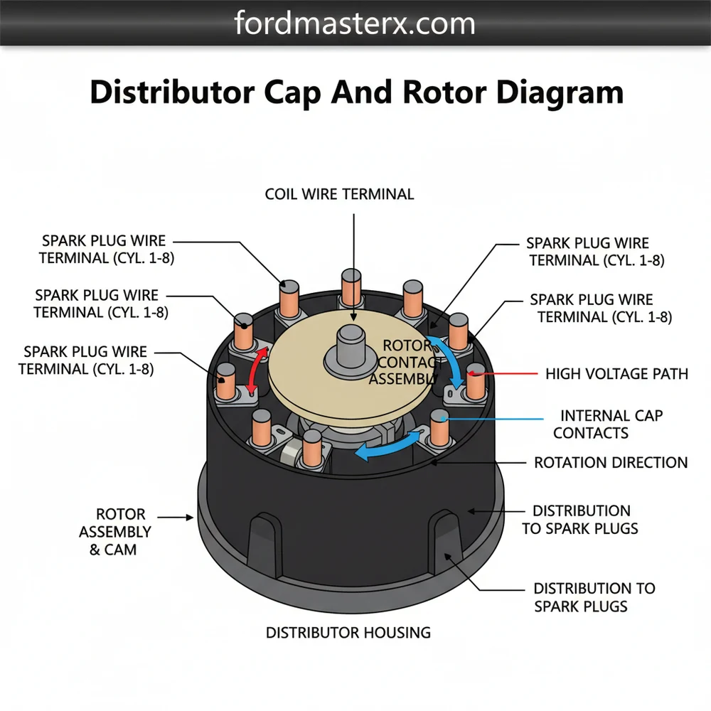
A comprehensive distributor cap and rotor diagram provides a visual breakdown of several critical components that must function in perfect harmony. At the center of the diagram is the distributor cap, usually a dome-shaped component made of high-dielectric strength plastic or composite material. The primary feature of the cap is the set of electrodes. There is one central terminal, which receives voltage from the ignition coil via a heavy-duty wire, and several outer terminals—one for each cylinder in your engine. For example, a V8 engine diagram will display eight perimeter terminals, while a four-cylinder engine layout will show four.
The internal architecture of the cap includes a spring-loaded carbon brush. This brush is located on the underside of the center terminal and makes constant physical contact with the center of the rotor. The rotor itself is a small, rotating arm typically made of plastic with a metal contact strip on top. As the engine turns, the distributor shaft spins the rotor. The metal tip of the rotor passes within a fraction of an inch of the outer electrodes inside the cap. The high-voltage current jumps this small gap, traveling through the spark plug wire to the engine.
Variations in these diagrams often occur based on the ignition system’s specific design. Some modern “HEI” (High Energy Ignition) systems integrate the ignition coil directly into the top of the distributor cap, meaning the diagram will show the coil leads connecting internally rather than through an external wire. Additionally, diagrams will frequently include an “indexing notch” or a “keyway,” which ensures the cap can only be bolted onto the distributor housing in one specific orientation. This is crucial for maintaining proper ignition timing. Many schematics also highlight the “firing order,” which is the numerical sequence in which the spark plugs ignite. This sequence is rarely sequential (e.g., 1-2-3-4) and is usually a specific pattern like 1-8-4-3-6-5-7-2 for many V8 engines.
[DIAGRAM_PLACEHOLDER: A detailed 2D schematic showing a top-down view of a distributor cap with labeled terminals (1 through 8), a central coil input, an internal rotor arm with a metal tip, and an arrow indicating the direction of rotation (clockwise). Labels include: Carbon Brush, Rotor Tip, Electrode, Indexing Notch, and Spark Plug Lead.]
Step-by-Step Guide to Reading and Implementing the Diagram

Interpreting a distributor cap and rotor diagram requires a methodical approach. To use these diagrams effectively for a repair or a tune-up, follow these specific steps to ensure your engine remains in perfect sync.
- ✓ Identify the #1 Cylinder Terminal: Look for a mark on the diagram or the physical cap (often a small “1” or a raised bump) that indicates the starting point for the firing order.
- ✓ Determine Rotation Direction: Observe the arrow on the diagram showing if the rotor moves clockwise or counter-clockwise. This is vital for plugging wires in the correct sequence.
- ✓ Map the Firing Order: Starting from terminal #1, follow the rotation direction and assign the remaining wires based on your engine’s specific firing order.
- ✓ Check for Indexing: Locate the alignment tab on the diagram to ensure the cap sits correctly on the distributor base.
- ✓ Inspect Component Integrity: Use the diagram to identify the location of the carbon brush and internal electrodes to check for wear or corrosion.
To perform an actual replacement using the diagram, you will need a few basic tools: a screwdriver (flathead or Phillips, depending on the mounting screws), a set of sockets, a permanent marker, and possibly a spark plug wire puller. Before beginning, always disconnect the negative battery terminal to prevent accidental electrical shocks or shorts.
Never remove all spark plug wires at once without labeling them. If you lose the sequence, the engine will not start or may backfire violently, causing damage. Always use your diagram to verify each wire’s destination.
The process starts by comparing your physical distributor to the diagram. Locate the terminal for cylinder number one. If you are replacing the cap, it is best to move one wire at a time from the old cap to the new one, following the layout shown in the schematic. Once the wires are transferred, unscrew the cap and lift it off to reveal the rotor. The rotor usually slides off the shaft or is held by two small screws. Install the new rotor, ensuring it keys into the shaft correctly, then install the new cap. Ensure the indexing notch is perfectly seated before tightening the screws to prevent the rotor from hitting the internal electrodes.
Common Issues and Troubleshooting with the Diagram

A distributor cap and rotor diagram is a powerful diagnostic tool when your vehicle experiences ignition problems. One of the most frequent issues is “carbon tracking.” This occurs when high voltage finds a path across the surface of the cap, usually due to moisture or dirt, creating a literal burnt line of carbon. The diagram helps you identify which terminals are being bypassed, explaining why a specific cylinder might be misfiring.
Another common problem is terminal corrosion. Over time, the metal electrodes inside the cap and the tip of the rotor develop a crusty green or white oxidation. This increases electrical resistance, leading to a weak spark. By referring to the diagram, you can systematically check each electrode. If the diagram shows a specific terminal corresponds to a cylinder that is throwing a fault code, you know exactly where to look for physical damage. Cracks in the cap are also a concern; even a hairline fracture can allow moisture to enter, leading to hard starts in damp weather. If your engine cranks but won’t start, use the diagram to verify that the coil wire is properly seated in the center terminal and that the rotor is actually spinning when the engine turns.
Apply a small amount of dielectric grease to the inside of the spark plug wire boots before connecting them to the distributor cap. This prevents moisture intrusion and makes future removal much easier.
Best Practices and Maintenance Recommendations
To ensure the longevity of your ignition system, regular maintenance is key. Most automotive experts recommend inspecting the distributor cap and rotor every 15,000 to 30,000 miles, or according to your vehicle manufacturer’s specific intervals. When purchasing replacement parts, always opt for components with brass terminals rather than aluminum. Brass is a superior conductor and is much more resistant to the corrosion that causes ignition failure.
When implementing the configuration shown in your distributor cap and rotor diagram, ensure that the spark plug wires are routed neatly and secured in plastic looms. If wires are allowed to drape over hot engine components or rub against moving parts, the insulation will fail, leading to arcing and misfires. Furthermore, always check the condition of the distributor shaft itself. If you notice oily residue inside the cap, it may indicate a failing internal seal in the distributor housing, which will quickly ruin a new cap and rotor set.
Cost-saving advice for DIY enthusiasts: don’t just replace the cap; always replace the rotor at the same time. These two components wear out at roughly the same rate, and using an old rotor with a new cap can lead to uneven wear and premature failure. By keeping a printed copy of your specific distributor cap and rotor diagram in your glovebox or workshop manual, you ensure that you are always prepared to handle ignition system repairs with confidence and precision. This simple schematic is the key to maintaining a smooth-running engine and avoiding costly professional diagnostic fees.
In conclusion, mastering the use of a distributor cap and rotor diagram is a fundamental skill for any vehicle owner or amateur mechanic. By understanding the system configuration and the structural relationship between the cap, rotor, and firing order, you can effectively troubleshoot engine issues and perform routine maintenance that keeps your vehicle on the road. Always remember to prioritize safety, use high-quality components, and follow the schematic layout exactly to ensure peak ignition performance.
Frequently Asked Questions
Where is the distributor cap located?
The distributor cap is typically located on the engine block or cylinder head, connected to the spark plug wires. It sits atop the distributor housing, which is driven by the camshaft. Finding this component is easy; just follow the thick ignition wires from the spark plugs back to their source.
What does a distributor cap and rotor diagram show?
This diagram provides a clear view of the ignition system’s configuration. It displays the layout of the cap terminals, the rotation direction of the rotor, and how each wire connects to specific cylinders. It is essential for ensuring the correct firing order is maintained during repairs or maintenance.
How many connections does a distributor cap have?
A distributor cap typically features one central input terminal for the ignition coil wire and several output terminals corresponding to the number of engine cylinders. For example, a V8 engine cap has eight outer terminals and one center post, forming a specific structure to facilitate sequential spark distribution.
What are the symptoms of a bad distributor cap?
Common symptoms include engine misfiring, difficulty starting, rough idling, and stalling. You may also hear unusual tapping noises from the engine bay. Inspecting the component’s internal structure for cracks, moisture, or carbon tracking between terminals often reveals the need for a replacement to restore system efficiency.
Can I replace this myself?
Yes, replacing these parts is a common DIY task. By using a distributor cap and rotor diagram, you can ensure each wire returns to its correct terminal. It requires basic tools and patience to avoid mixing up the firing order, making it an accessible project for most vehicle owners.
What tools do I need for this task?
To replace or inspect these components, you usually need a screwdriver (flat-head or Phillips) or a small socket set to remove the mounting screws. You may also need a clean rag to wipe the mounting surface and a marker to label wires if the diagram is not present.