Combined Brake and Turn Signal Wiring Diagram: Easy Setup
A combined brake and turn signal wiring diagram illustrates how a single bulb filament or LED strip handles both functions using a turn signal switch or logic module. It typically routes the hot wire through a flasher relay and brake switch to a common terminal, ensuring signals override brakes when turning.
📌 Key Takeaways
- Synchronizes brake and turn functions on a single bulb filament
- The turn signal switch is the most critical component for signal priority
- Always ensure a solid chassis ground to prevent dim or flickering lights
- Use a 3-to-2 wire converter when towing trailers with separate systems
- Essential for troubleshooting rear lighting failures in vintage and modern vehicles
When attempting to repair or install lighting on a vehicle or trailer, having an accurate combined brake and turn signal wiring diagram is absolutely essential for a safe and functional result. This specific type of circuit is unique because it requires a single bulb filament or LED bank to perform two distinct functions: glowing steadily for braking and flashing for signaling a turn. Without a proper diagram, you risk cross-wiring the system, which can lead to blown fuses, melted insulation, or confusing light patterns that may cause road accidents. In this comprehensive guide, you will learn how to identify various wire colors, locate specific terminals like the common terminal, and understand the flow of electricity from the power source through the traveler wire to the rear lamps. By the end of this article, you will have the technical knowledge required to successfully wire a combined system with confidence.
In a combined system, the turn signal switch acts as a “logic gate.” When you are not signaling, it allows the brake light voltage to pass through to both rear lamps. When you activate a turn signal, the switch interrupts the steady brake power on that specific side and replaces it with a pulsing signal from the flasher relay.
Understanding the Combined Brake and Turn Signal Layout
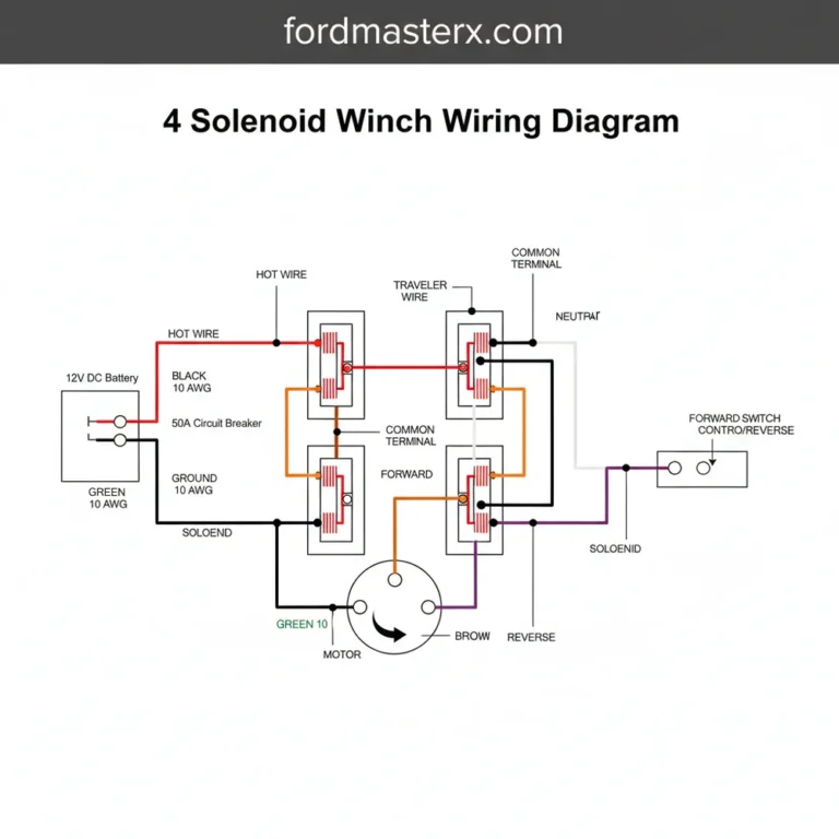
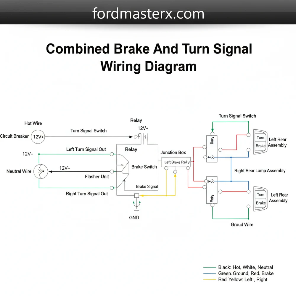
The combined brake and turn signal wiring diagram represents a sophisticated electrical loop designed to maximize efficiency. Unlike separate systems where the brake and turn signals have their own dedicated bulbs and wires, the combined system merges these functions into a primary circuit. The diagram typically begins at the vehicle’s fuse block, where a hot wire carries 12-volt DC power to the brake light switch and the turn signal flasher. One of the most critical components in this diagram is the turn signal switch, which serves as the central hub where the brake and turn signals are integrated.
In a standard 4-way trailer or automotive setup, the diagram uses specific color codes to identify functions. The ground wire is almost universally white and must be securely fastened to the metal chassis to complete the circuit. The brown wire typically handles the tail lights (running lights), while the green wire is designated for the right-hand turn and brake signal, and the yellow wire handles the left-hand turn and brake signal. When looking at the diagram, you will notice that the green and yellow wires are essentially traveler wires that carry the “combined” command from the switch at the front of the vehicle to the sockets at the rear.
The terminals in these diagrams are often labeled to prevent confusion. For example, a common terminal on the turn signal switch receives the output from the brake light switch. Inside the switch, this power is distributed to the left and right outputs. If you are using a terminal block for your connections, you might encounter a brass screw or a silver-plated terminal. Historically, the brass screw is used for the hot wire or “load” side of a connection, while silver or zinc-plated screws are associated with the neutral wire or ground in some AC-DC converter contexts, though in standard DC automotive wiring, the brass-colored terminal remains the standard for positive connections.
Step-By-Step Installation and Wiring Guide
To successfully implement a combined brake and turn signal wiring diagram, you must follow a methodical sequence to ensure every connection is secure and the logic of the circuit is preserved. Before beginning, ensure you have gathered the necessary tools and understand the specifications of your vehicle’s electrical system.
- ✓ Multimeter or Test Light (12V)
- ✓ Wire Strippers and Crimping Tool
- ✓ Heat Shrink Tubing and Electrical Tape
- ✓ 14 or 16 Gauge Automotive Grade Wire
- ✓ High-Quality Connectors (Ring terminals and butt connectors)
Step 1: Disconnect the Battery
Safety is the first priority. Locate your vehicle’s battery and disconnect the negative terminal. This prevents accidental short circuits that could damage the sensitive electronics in your turn signal switch or blow high-amperage fuses while you are manipulating the hot wire.
Step 2: Identify and Route the Hot Wire
Using your wiring diagram, identify the hot wire coming from the fuse panel. This wire provides the necessary voltage for the entire system. Route this wire to the input side of your brake light switch (usually mounted near the brake pedal) and to the input of your flasher relay.
Step 3: Connect to the Common Terminal
The output from your brake light switch must be routed to the common terminal on your turn signal switch. This is the “bridge” that allows your brake signal to be shared by the turn signal circuitry. If your switch uses a terminal block, ensure the wire is wrapped securely around the brass screw or inserted fully into the terminal before tightening.
Step 4: Install the Traveler Wires
From the output side of the turn signal switch, you will run two traveler wires toward the rear of the vehicle. One traveler wire (usually yellow) goes to the left-side lamp, and the other (usually green) goes to the right-side lamp. These wires are responsible for carrying both the steady brake voltage and the pulsing turn signal voltage.
Step 5: Establish a Solid Ground
Every lighting fixture requires a reliable ground wire to function. In many combined systems, the white wire serves as the ground. Attach this wire to a clean, unpainted section of the vehicle’s frame. A poor ground is the most common cause of dim lights and erratic signal behavior.
Step 6: Test Voltage and Continuity
Before finalizing your connections with heat shrink, reconnect the battery and use a multimeter to check the voltage at each lamp socket. With the brakes applied, you should see a steady 12V. With the turn signal on, the meter should pulse. Ensure that the gauge of the wire is sufficient for the load; 16 gauge is standard for most passenger vehicles, while 14 gauge is better for long trailer runs to prevent voltage drop.
Never substitute automotive wire with household wire. Household wire (ROMEX) is designed for AC current and is often solid core, which can fatigue and snap due to the vibrations of a moving vehicle. Always use stranded, copper, automotive-grade wire for these circuits.
Common Issues and Troubleshooting

Even with a perfect combined brake and turn signal wiring diagram, issues can arise during the installation or over time as the vehicle is used. One of the most frequent problems is “hyper-flashing,” where the turn signal blinks much faster than normal. This usually occurs when switching from incandescent bulbs to LEDs without installing a load-resistor or an LED-compatible flasher relay, as the lower voltage draw tricks the system into thinking a bulb is burnt out.
Another common issue is “back-feeding,” where applying the brakes causes the dash lights or the front turn signals to illuminate. This is often a sign of a failed turn signal switch or an incorrect connection at the common terminal. If you find that one side works perfectly but the other side is dim or non-responsive, check the ground wire for that specific housing. Since the brake and turn signals share the same wire and filament, a failure in the traveler wire will result in the loss of both functions on that side of the vehicle.
If your lights are completely unresponsive, check the voltage at the fuse box first. Use your diagram to trace the hot wire path. If power exists before the switch but not after, the switch itself is likely the culprit. Troubleshooting becomes much simpler when you use the diagram to isolate specific segments of the circuit, testing each terminal and screw for proper connectivity.
Tips and Best Practices for Wiring
To ensure the longevity of your combined brake and turn signal system, follow these professional best practices. First, always use dielectric grease on your bulb sockets and terminal connections. This non-conductive grease prevents moisture from entering the connection points, which stops corrosion and “green crust” from forming on your brass screw terminals or pin connectors.
When running traveler wires along a trailer frame, use plastic loom or conduit to protect the wires from road debris and chafing. Secure the loom every 12 to 18 inches with UV-resistant cable ties to prevent sagging.
When selecting components, prioritize quality. While it may be tempting to save costs by using thinner wire, sticking to the recommended gauge prevents overheating and ensures that the full 12 volts reach the rear of the vehicle. For long trailers, stepping up to a 14-gauge wire for the ground and main power lines can significantly improve brightness. Additionally, if you are building a system from scratch, consider using a dedicated power converter if your tow vehicle has a 5-wire system (separate brake and turn) and your trailer has a 4-wire system (combined).
Finally, always double-check your connections against the combined brake and turn signal wiring diagram before sealing them. A few minutes spent verifying the color codes and terminal placements can save hours of troubleshooting later. Proper maintenance includes checking the ground wire annually for rust and ensuring that the traveler wires remain securely fastened and free of cracks or brittle insulation. By following these guidelines and utilizing a clear diagram, you can maintain a safe, reliable lighting system for years to come.
Step-by-Step Guide to Understanding the Combined Brake And Turn Signal Wiring Diagram: Easy Setup
Identify the power source and hot wire from the fuse box to the brake switch and turn signal flasher.
Locate the common terminal on the turn signal switch that integrates inputs from both the brake pedal and flasher.
Understand how the traveler wire or signal lead carries the combined output from the switch to the vehicle’s rear.
Connect the ground wire firmly to the vehicle chassis to ensure a complete and stable circuit for the bulbs.
Verify that the neutral wire or return path is isolated to prevent feedback loops in the lighting system.
Complete the installation by testing both turn signals while the brake pedal is depressed for proper signal overriding.
Frequently Asked Questions
Where is the turn signal switch located?
The turn signal switch is typically located on the steering column, integrated into the multi-function lever. In some older vehicles, it may be found behind the steering wheel. This central location allows it to intercept the hot wire from the flasher and brake switch before sending signals to the rear.
What does this wiring diagram show?
This wiring diagram shows the electrical path from the power source through the brake and turn signal switches to the rear lamps. It illustrates how the system prioritizes the flashing turn signal over the steady brake light signal at a common terminal, ensuring clear communication to other drivers on the road.
How many connections does a standard bulb have?
A standard dual-filament bulb usually has three main connections: one for the tail lights, one for the combined brake/turn signal, and a dedicated ground wire. In complex systems, you may see a traveler wire setup that routes different voltage levels to manage the intensity of the illumination during operation.
What are the symptoms of a bad turn signal switch?
Symptoms of a failing system include lights that won’t flash, signals that stay solid when the brake is pressed, or complete loss of rear lighting. This often indicates a blown fuse, a faulty ground wire, or a short circuit in the hot wire leading to the common terminal inside.
Can I install this wiring system myself?
Yes, you can install or repair this wiring yourself with a clear diagram and basic electrical knowledge. It is essential to ensure every connection is secure and the neutral wire or return path is clean. Always disconnect the battery before starting to prevent accidental shorts or damage to components.
What tools do I need for this wiring task?
To complete this task, you will need a multimeter to test for continuity, wire strippers, crimping tools, and electrical tape or heat shrink tubing. A test light is also helpful for verifying power at the hot wire and ensuring the common terminal is receiving the correct voltage signals.