Bad Throttle Position Sensor Symptoms in Ford Vehicles: A Complete Diagnostic Guide 2026
The throttle position sensor (TPS) functions as the primary translation interface between driver input and engine output. In modern internal combustion engines, the TPS monitors the precise angle of the throttle blade (or butterfly valve) and continuously transmits this telemetry to the Powertrain Control Module (PCM). The PCM subsequently utilizes this real-time data, which is measured in increments as precise as a hundredth of a volt, to dynamically adjust the air-fuel mixture, govern ignition timing, and dictate automatic transmission shift scheduling.
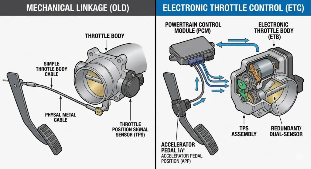
Historically, automotive engineering relied on mechanical throttle linkages connected directly from the accelerator pedal to the carburetor or throttle body. However, the integration of Electronic Throttle Control (ETC), commonly referred to as “drive-by-wire,” fundamentally altered this architecture. In an ETC system, the mechanical cable is replaced by an Accelerator Pedal Position (APP) sensor and an electronic throttle body (ETB).
The ETB houses an internal electric actuator motor and redundant throttle position sensors that verify the blade’s physical position against the driver’s pedal input. When a discrepancy arises between the commanded throttle position and the actual blade angle, the vehicle experiences a cascade of drivability issues, triggering specific diagnostic protocols and fail-safe modes.
The Complete Guide to Bad Throttle Position Sensor Symptoms
Diagnose erratic idling, stalling, and acceleration issues before they leave you stranded. A data-driven analysis for mechanics and DIY enthusiasts.
🔍 What is a Throttle Position Sensor (TPS)?
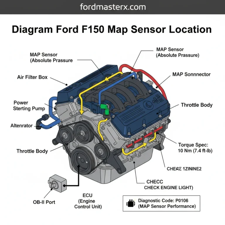
The Throttle Position Sensor (TPS) is a critical engine management component located on the throttle body. It acts as a potentiometer, continuously monitoring the angle of the throttle butterfly valve. As you press the accelerator pedal, the valve opens, and the TPS sends a precise voltage signal to the Engine Control Module (ECM) or Powertrain Control Module (PCM). The computer uses this data, alongside input from the Mass Air Flow (MAF) sensor and Manifold Absolute Pressure (MAP) sensor, to calculate the exact air-fuel mixture and ignition timing required for optimal engine performance.
When this sensor begins to fail, the ECM receives erratic or missing data, resulting in a miscalculated air-fuel ratio. This mismatch immediately triggers a cascade of drivability issues. Understanding these symptoms is the first step in restoring your vehicle’s performance. For further reading on sensor operation, consult the technical resources at Standard Motor Products.
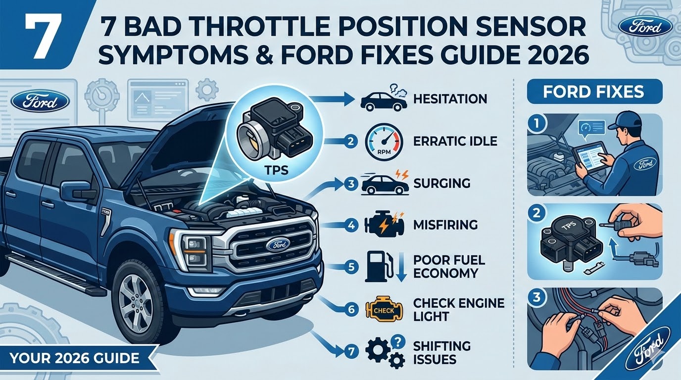
📊 The 7 Most Common Bad TPS Symptoms
A failing TPS rarely dies silently. It manifests through noticeable drivability complaints. Based on aggregate diagnostic data from repair facilities across North America, certain symptoms are highly indicative of a TPS voltage irregularity. The chart below illustrates the relative frequency of these symptoms reported by drivers experiencing TPS failure.
Frequency of Reported TPS Symptoms
Percentage of vehicles exhibiting specific symptoms prior to TPS replacement
1. Hesitation & Stumbling During Acceleration
The most prevalent symptom. As you press the gas pedal, the engine may stumble or hesitate before catching up. This occurs because the ECM is not receiving a smooth, linear voltage increase from the TPS, causing a lean fuel condition at tip-in.
2. Rough or Erratic Idle
If the TPS has a worn spot at the closed-throttle position, it sends fluctuating signals to the computer while your foot is off the pedal. This causes the engine RPMs to surge up and down unpredictably while stopped.
3. Engine Stalling
Severe cases of TPS failure can cause the computer to miscalculate the air-fuel ratio so drastically that the engine stalls out entirely, particularly when coming to a stop or idling.
💻 Diagnostic Trouble Codes (DTCs)
When the ECM detects a signal from the TPS that falls outside normal parameters, it triggers the Check Engine Light. According to OBD-Codes.com, retrieving these P-codes is the most definitive diagnostic step.
| OBD-II Code | Definition / Meaning |
|---|---|
| P0120 | TPS “A” Circuit Malfunction |
| P0121 | TPS “A” Circuit Range/Performance Problem |
| P0122 | TPS “A” Circuit Low Input (Short to ground) |
| P0123 | TPS “A” Circuit High Input (Short to voltage) |
| P0124 | TPS “A” Circuit Intermittent |
📈 TPS Failure Probability by Mileage
Throttle position sensors are wear items. The internal carbon traces of the potentiometer degrade over time due to constant friction and engine bay heat. This chart illustrates the increasing probability of failure as vehicle mileage accumulates.
Data represents a generalized wear curve for carbon-contact potentiometers.
🔧 How to Test a Throttle Position Sensor
Before replacing the sensor, it is crucial to verify its failure using a digital multimeter (DMM). A visual inspection should also be performed to ensure the wiring harness is not damaged or corroded. Follow this systematic testing flow.
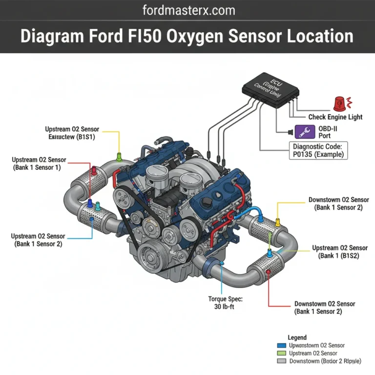
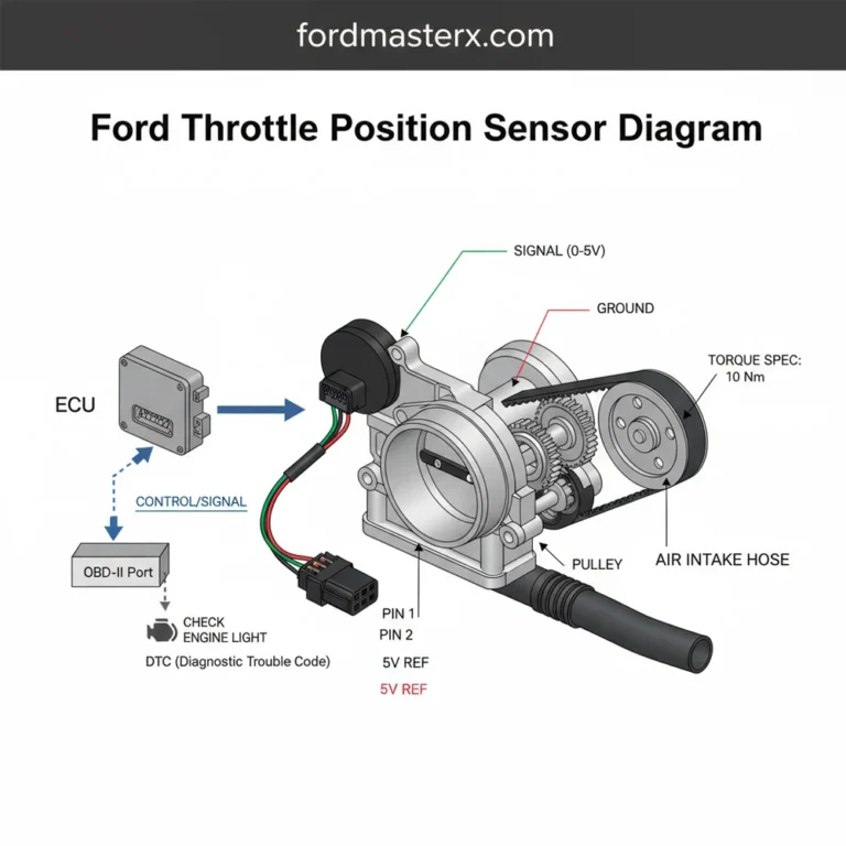
Locate the Sensor
Find the TPS mounted on the side of the throttle body unit, directly connected to the butterfly valve shaft.
Check Reference Voltage
Turn ignition ON (engine off). Probe the 5-volt reference wire. It should read approximately 5.0V from the ECM.
Test Signal Wire
Probe the signal wire. At closed throttle, it should read roughly 0.5V to 0.9V depending on the exact vehicle make.
Sweep Test
Slowly open the throttle to Wide Open Throttle (WOT). Voltage must increase smoothly to ~4.5V with no dropouts.
💰 Average TPS Replacement Cost Breakdown
If your diagnostic tests confirm a faulty sensor, replacement is necessary. The cost varies significantly depending on whether the TPS is a standalone component or integrated directly into an electronic throttle body (common in modern “Drive-by-Wire” vehicles). The data below represents national averages for a standalone sensor replacement.
Total Average Cost: $185
-
OEM Part Cost ($75 – $120) Always opt for Original Equipment Manufacturer parts for sensors. Aftermarket sensors frequently fail out of the box or lack proper calibration.
-
Labor Costs ($80 – $110) Typically billed as 0.5 to 1.0 hours of labor. This includes removing the air intake, swapping the sensor, and clearing OBD-II codes.
-
Taxes & Shop Fees ($15 – $25) Standard environmental and shop supply fees applied by professional repair facilities.
✔ DIY Savings Tip
Replacing a standalone TPS is an excellent beginner DIY project requiring only basic hand tools, potentially saving you over $100 in labor.
Core Bad Throttle Position Sensor Symptoms
When the TPS begins to broadcast irrational, erratic, or entirely absent data to the PCM, the vehicle will manifest several severe operational symptoms. Because the TPS dictates asynchronous fuel enrichment—acting as the digital equivalent of a carburetor’s mechanical accelerator pump—any signal delay causes immediate air-fuel ratio imbalances.
Engine Hesitation and Drivability Degradation
The most prominent symptom of TPS failure is hesitation or stumbling during acceleration. If the TPS signal contains a voltage dropout due to internal sensor wear, the PCM fails to command the fuel injectors to increase their pulse width as the throttle opens. Consequently, a massive influx of unmetered air enters the intake manifold without the corresponding fuel, creating an extreme lean condition. This air-fuel imbalance causes the engine to stumble, surge unpredictably, or completely lack the power necessary to accelerate past a given speed. In vehicles equipped with a faulty TPS, the engine may even rev uncontrollably when the gas pedal is not depressed, creating a significant driving hazard.
Idle Instability and Stalling
The TPS is heavily relied upon to manage idle air control parameters. When the throttle is fully closed, the TPS must register a stable base voltage to command the PCM into its idle strategy. If the sensor transmits a fluctuating voltage due to internal corrosion or micro-vibrations, the PCM continuously alters the ETB motor position, causing the engine idle to surge rhythmically. If the PCM receives an erroneous signal indicating the throttle is open when it is actually physically closed, it may cut fuel or incorrectly adjust timing, leading to sudden engine stalling at traffic lights or during low-speed maneuvers.
The Wrench Light vs. The Check Engine Light
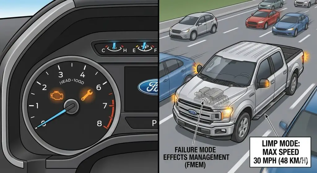
In Ford vehicles, drivers are often confronted with the illumination of an amber “Wrench Light” alongside or instead of the standard Check Engine Light (CEL). The CEL is mandated by OBD-II emission standards and generally illuminates when an anomaly affects tailpipe emissions. The Wrench Light, however, is Ford’s proprietary Powertrain Malfunction Indicator. It specifically denotes a severe failure within the Electronic Throttle Control (ETC) system or the transmission. When a TPS voltage correlation error occurs, the PCM triggers the Wrench Light and immediately commands Failure Mode Effects Management (FMEM), colloquially known as Limp Mode.
Failure Mode Effects Management (Limp Mode)
Under FMEM, the PCM recognizes that it can no longer trust the throttle position data. To prevent unintended acceleration—a severe safety hazard that has led to several(https://www.ford.com/support/recalls/)—the PCM disables the electronic throttle actuator. The throttle blade defaults to a mechanically spring-loaded rest position, which is slightly open to allow just enough air for a high idle. Engine RPM is artificially limited, and the vehicle crawls at a maximum speed of approximately 20 to 30 mph. During this phase, power steering and braking remain fully functional, but engine power is severely restricted until the fault is repaired or the PCM is power-cycled.
Potentiometer vs. Hall-Effect Sensors
Throttle position sensors are generally categorized into two distinct engineering topologies: potentiometer-based sensors and Hall-effect sensors. The physical properties of these sensors dictate their lifespan, failure modes, and operational accuracy.
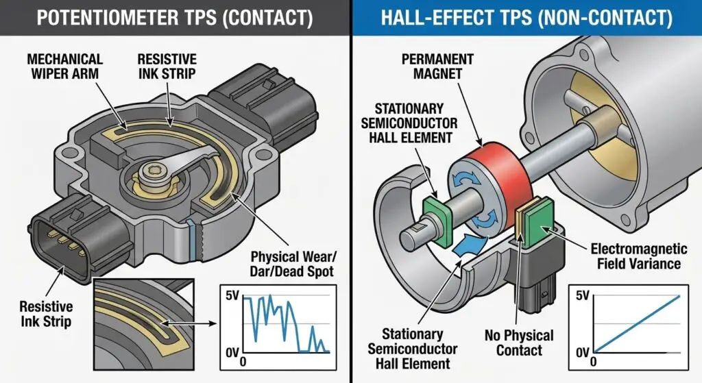
A potentiometer TPS operates as a variable resistor. It consists of a resistive ink strip and a mechanical wiper arm that rotates in tandem with the throttle shaft. As the throttle opens, the wiper sweeps across the resistive strip, altering the electrical resistance and modifying the voltage signal returned to the PCM, which typically ranges from $0.5V$ at idle to $4.5V$ at wide-open throttle. While cost-effective and structurally simple, potentiometers suffer from mechanical wear. Years of micro-vibrations and sweeping across the same localized area degrade the resistive strip, creating physical dead spots. When the wiper hits a dead spot, the voltage drops to zero, causing the PCM to momentarily calculate a closed throttle, resulting in sudden engine hesitation.
Conversely, Hall-effect sensors utilize electromagnetic fields rather than physical contact. A permanent magnet is attached to the throttle shaft, rotating within the proximity of a stationary Hall-effect semiconductor. As the magnetic field’s orientation changes, it induces a proportional voltage change in the semiconductor. Because there is no physical friction between moving parts, Hall-effect sensors eliminate mechanical wear, offering superior longevity, higher signal fidelity, and absolute immunity to physical dead spots.
| Operational Metric | Potentiometer-Based TPS | Hall-Effect TPS |
| Operational Principle | Variable electrical resistance via a physical wiper | Electromagnetic field variance |
| Primary Advantage | Simple design architecture, lower manufacturing cost | High precision, no physical wear, extreme durability |
| Primary Disadvantage | Prone to friction wear, creates voltage dead spots over time | Higher initial cost, complex internal circuitry |
| Common Failure Mode | Degraded resistive strip causing erratic voltage signaling | Magnet degradation or internal circuit board failure |
| Signal Output Type | Analog voltage ($0.5V – 4.5V$) | Analog or Digital (Pulse Width Modulated) |
Dual-Signal Redundancy and Diagnostic Trouble Codes
To facilitate accurate diagnosis, the PCM logs specific Diagnostic Trouble Codes (DTCs) when a TPS failure is detected. Modern Ford electronic throttle bodies utilize a dual-potentiometer redundancy system designed strictly for safety. These two internal sensors, identified as TP1 and TP2, operate on an inverted voltage algorithm.
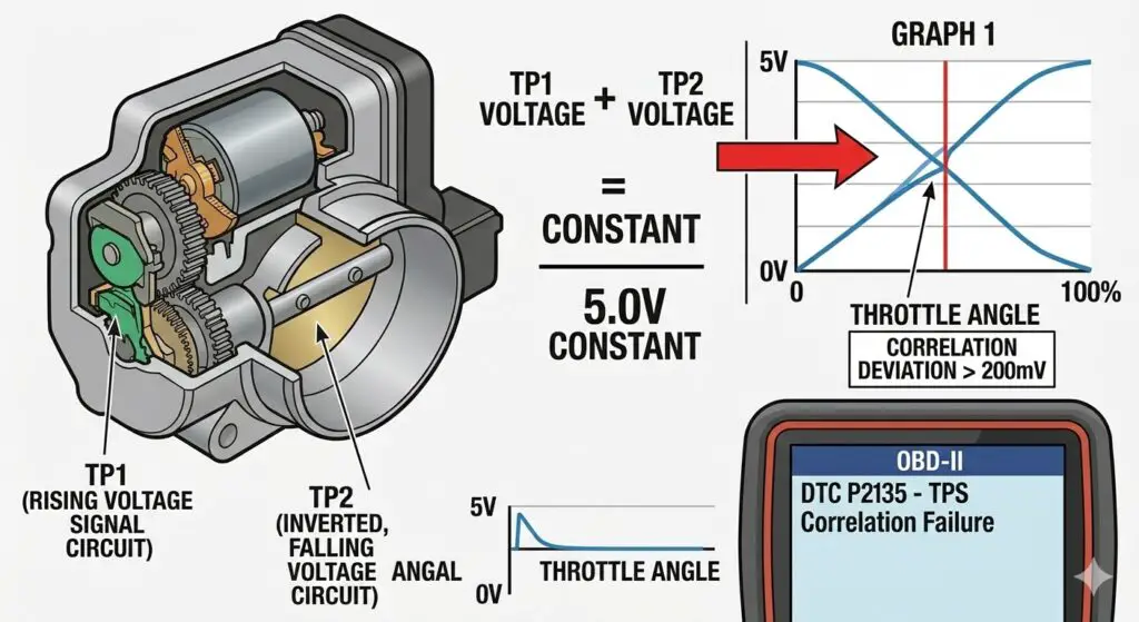
As the throttle opens, the voltage of TP1 increases while the voltage of TP2 decreases proportionally. The PCM relies on a mathematical constant: the sum of the TP1 voltage and the TP2 voltage must always equal approximately $5.0V$. If the sum deviates by more than $200mV$ for a predetermined number of milliseconds, the PCM instantly recognizes a sensor failure, aborts throttle control, and logs a correlation code.
| OBD-II Code | Definition | Diagnostic Indication and PCM Logic |
| P0121 | TPS “A” Circuit Range/Performance | The TPS voltage does not match the expected value for a specific RPM and Manifold Absolute Pressure (MAP). Indicates a biased sensor or physical dead spot. |
| P0122 | TPS “A” Circuit Low Input | The sensor voltage drops below the minimum threshold (typically $<0.17V$). Often indicates a short to ground or a completely severed signal wire. |
| P0123 | TPS “A” Circuit High Input | The sensor voltage exceeds the maximum threshold (typically $>4.5V$ at idle). Indicates a short to voltage or a loss of the sensor ground circuit. |
| P2135 | TPS / Pedal Position Sensor A/B Correlation | The inverse voltage sum of TP1 and TP2 deviates from the $5.0V$ constant. A direct indicator of internal ETB failure or wiring harness chafing. |
| P2111 | Throttle Actuator Control System – Stuck Open | The PCM commands the throttle to close, but the TPS reports it remains open. Can be caused by severe carbon buildup or mechanical gear failure. |
| P2112 | Throttle Actuator Control System – Stuck Closed | The PCM commands the throttle to open, but the TPS reports no movement. Usually points to internal actuator motor failure or extreme throttle body coking. |
Technical Service Bulletins: Ford TSB 16-0139 and TSB 10-21-6
Between 2010 and 2016, a widespread manufacturing anomaly plagued Ford’s Electronic Throttle Bodies across multiple engine platforms, including the 3.5L EcoBoost, 3.7L V6, and 5.0L Coyote V8. The issue became so pervasive that the National Highway Traffic Safety Administration (NHTSA) opened investigations, and Ford released several Technical Service Bulletins, culminating in and an earlier iteration, TSB 10-21-6.
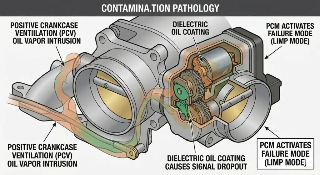
The underlying pathology involves oil vapor and contaminants from the Positive Crankcase Ventilation (PCV) system bypassing the throttle blade shaft seals. Over time, this contaminated oil infiltrates the sealed electronic compartment housing the internal TPS contacts and the DC actuator motor. The oil acts as a dielectric barrier, disrupting the electrical continuity of the TP1 and TP2 sweeps. When the signal drops out intermittently, the PCM instantly logs codes P2111, P2112, or P2135 and throws the vehicle into a violent FMEM Limp Mode.
For vehicles affected by TSB 16-0139, which includes highly popular models such as the F-150, Explorer, Mustang, and Edge, the official repair procedure strictly mandates the complete replacement of the electronic throttle body assembly. The TPS in these modern ETBs is permanently integrated into the housing and cannot be serviced, cleaned, or replaced independently of the main unit.
TPS Impact on 6R80 and 10R80 Shift Scheduling
A widely misunderstood element of automotive diagnostics is the profound relationship between the throttle position sensor and automatic transmission behavior. In Ford vehicles equipped with the 6R80 six-speed and 10R80 ten-speed automatic transmissions, shifting is not dictated by mechanical governors or simple vacuum modulators, but rather by complex torque-based algorithms.
The PCM dynamically adjusts transmission line pressure and shift timing based on the concept of driver commanded torque. This mathematical calculation requires two primary inputs: the Accelerator Pedal Position (APP) sensor, representing what the driver is requesting, and the Throttle Position Sensor, representing what the engine is physically delivering.
When a TPS signal becomes noisy or drops out entirely, the PCM immediately loses its ability to calculate precise engine load. As a self-preservation mechanism, the transmission control software defaults to maximum line pressure to prevent clutch slippage. This results in brutally harsh, neck-snapping shifts, particularly in the lower gears. Furthermore, incorrect TPS data can cause the 10R80 to miscalculate the necessary gear for the current road load, leading to unpredictable gear skipping, delayed engagements when shifting from Park to Drive, or dramatic RPM flares between gear changes.
These symptoms are frequently misdiagnosed as catastrophic internal transmission failures. In the Ford 6R80, a known defect exists within the Lead Frame, which is a molded plastic assembly housing the Transmission Control Module (TCM), speed sensors, and range sensors. When the lead frame fails, the transmission drops into limp mode, effectively mimicking the exact symptoms of a P2135 TPS correlation failure. Similarly, the 10R80 suffers from a mechanical flaw where the CDF clutch drum bushing slides out of position, causing massive internal pressure leaks and delayed shifts. Independent mechanics and dealerships frequently, and mistakenly, rebuild entire transmissions at the cost of thousands of dollars, only to realize the harsh shifting was caused by a faulty throttle body sending erratic load data to the PCM.
Diagnostic Protocols and Adaptive Learning Resets
Diagnosing a TPS failure begins with a visual inspection of the throttle body wiring harness. The connector leading to the ETB is highly susceptible to water intrusion, pin fretting, and wire chafing. The standard six-pin connector on a Ford F-150 Coyote V8 or Barra engine provides a $5V$ reference circuit, a sensor ground, the two motor control circuits, and the TP1 and TP2 signal returns. A digital multimeter must be used to verify the integrity of the $5V$ reference and the ground circuit. A sweep test, performed by manually pressing the accelerator pedal slowly to the floor with the key in the ON position and the engine OFF, should yield a smooth, uninterrupted voltage curve on a lab scope.
Replacing the TPS or the entire electronic throttle body does not immediately resolve the vehicle’s drivability issues. Over the lifespan of the previous, failing sensor, the PCM slowly altered its Keep Alive Memory (KAM) adaptive tables to compensate for the buildup of carbon and the degraded sensor voltage. When a new, clean throttle body is installed, it permits significantly more airflow at the same throttle angle, causing the engine to idle erratically or surge well above normal operating parameters.
To rectify this, an official Ford throttle body relearn procedure must be executed to recalibrate the baseline idle values and transmission shift schedules. First, the technician must clear the KAM. This is achieved by disconnecting the negative battery terminal and using a jumper wire to connect the negative battery cable to the positive terminal for two minutes, which fully discharges the PCM’s internal capacitors. Alternatively, a bidirectional scan tool or software like FORScan can be used to electronically clear the adaptive tables.
Once the memory is cleared, the battery is reconnected, and all heavy electrical accessories such as the air conditioning and headlights are turned off. The engine is started and allowed to idle undisturbed for fifteen minutes to reach normal operating temperature and establish base idle. Following this, the air conditioning is turned to maximum to introduce an accessory load, and the vehicle idles for an additional minute. The operator then depresses the brake, shifts the transmission into Drive, and holds the vehicle stationary for one minute to allow the PCM to learn the load-bearing idle target. Finally, the vehicle must be driven under light throttle, allowing the transmission to shift sequentially up to the highest gear, repeating this cycle several times so the transmission adaptive tables synchronize perfectly with the new TPS voltage curve.
Throttle Position Sensor Replacement Cost Analysis
The cost to rectify a bad throttle position sensor relies heavily on the age and physical architecture of the vehicle. On older Ford models, such as pre-2004 F-150s utilizing mechanical cable throttles, the TPS is a standalone sensor bolted to the side of the throttle body. This individual part is relatively inexpensive, and labor is minimal.
On newer models featuring Electronic Throttle Control, the TPS is integrated permanently into the throttle body assembly housing. When the internal TP1 or TP2 potentiometers fail, the entire throttle body must be discarded and replaced as a single unit. Fortunately, due to the ease of access at the top of the intake manifold, labor times are exceedingly low, averaging between 0.3 to 0.6 hours of professional shop time.
| Ford Vehicle Model | Model Year Range | Estimated Parts Cost | Estimated Labor Cost | Total Estimated Cost |
| Ford F-150 | 2004 – 2008 | $96 – $136 | $58 – $85 | $154 – $222 |
| Ford F-150 | 1990 – 1995 | $150 – $200 | $56 – $80 | $206 – $280 |
| Ford Explorer | 2009 – 2010 | $100 – $140 | $80 – $94 | $180 – $234 |
| Ford Focus | 2005 – 2011 | $40 – $60 | $42 – $46 | $82 – $106 |
| Ford F-250 Super Duty | 2011 – 2016 | $100 – $150 | $59 – $84 | $159 – $234 |
| Ford Mustang | 2005 – 2014 | $100 – $140 | $53 – $75 | $153 – $215 |
FAQs
Can a bad throttle position sensor cause the transmission to slip?
Yes. While a TPS failure does not directly cause mechanical clutch deterioration, it feeds critical engine load and torque data to the Powertrain Control Module. When the sensor data is corrupted, the transmission receives erratic line pressure commands, resulting in harsh shifts, gear skipping, and a sensation mimicking a slipping clutch or a failing lead frame.
What is the difference between an APP sensor and a TPS?
The Accelerator Pedal Position (APP) sensor is located on the gas pedal inside the vehicle cabin and measures the driver’s intended acceleration request. The Throttle Position Sensor (TPS) is located on the engine’s throttle body and measures the actual physical angle of the throttle blade. The PCM constantly compares these two sensors; if the APP commands fifty percent throttle but the TPS only reads fifteen percent, the system logs a correlation code and initiates a fail-safe mode.
Will a throttle position sensor failure always trigger a Check Engine Light?
Not necessarily. A sensor may develop a minute dead spot on its resistive strip that causes intermittent hesitation or a momentary stall without meeting the strict temporal parameters required by the PCM to log a hard diagnostic trouble code. These ghost codes or code-less failures require a live-data scan tool or an oscilloscope to diagnose properly, as the voltage dropout occurs faster than the standard OBD-II refresh rate can display.
Can I clean a throttle position sensor to fix it?
If the vehicle utilizes a standalone, externally mounted TPS, cleaning is impossible as the unit is a hermetically sealed potentiometer. However, if the issue stems from a sticky ETB blade triggering a P2111 code due to severe carbon buildup, cleaning the throttle bore with a specialized solvent and a soft brush can restore free movement and resolve the code. If oil has permeated the electronic housing as outlined in TSB 16-0139, cleaning the bore will not restore the internal circuit board, making replacement mandatory.