7 Way Trailer Plug Wiring Diagram Ford: Easy Setup Guide
The 7 way trailer plug wiring diagram ford maps out specific pin functions: the center pin handles reverse lights, while outer pins manage brakes, battery, and signals. You must connect the ground wire to a solid frame point, the hot wire for power, and ensure each traveler wire circuit correctly activates your trailer’s auxiliary functions.
📌 Key Takeaways
- Mapping correct pinouts for brakes, battery, and turn signals is essential for safety.
- The ground wire is the most critical component for completing the electrical circuit.
- Always disconnect the vehicle battery to prevent shorts during the installation process.
- Applying dielectric grease to the common terminal prevents moisture and corrosion buildup.
- Use this diagram when installing a new harness or diagnosing trailer lighting failures.
When you are preparing to tow a heavy load with your truck, having access to a correct 7 way trailer plug wiring diagram ford is essential for ensuring safety and functionality on the road. Ford vehicles are renowned for their towing capabilities, but the electrical interface between the vehicle and the trailer can be complex due to the various signals required for modern trailers. A proper diagram provides a visual map of the electrical pathways, ensuring that your brake lights, turn signals, electric brakes, and auxiliary power all function in perfect synchronization. By following the specific wiring standards for your Ford, you minimize the risk of electrical shorts or blown fuses that could leave you stranded. In this guide, you will learn how to identify each terminal, understand the specific color codes used by Ford, and master the installation process to ensure a reliable connection every time you hitch up.
Understanding the 7 Way Trailer Plug Component Breakdown
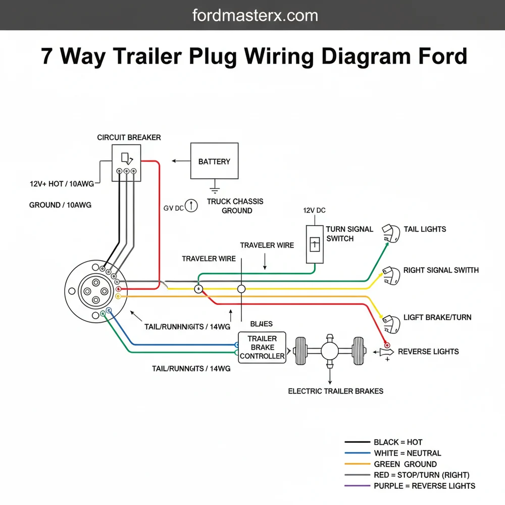
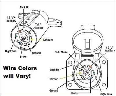
The 7-way trailer connector used on Ford trucks is often referred to as a “blade style” or “RV style” connector. Unlike smaller 4-flat or 5-flat connectors, the 7-way plug carries high-current signals and specialized data for electric brakes and reverse lights. The diagram for this plug is viewed from the perspective of the rear of the vehicle, looking into the face of the socket. Each of the seven pins is strategically placed to prevent cross-talk and to handle the specific voltage and current requirements of the trailer’s systems.
In a Ford-specific setup, the central pin usually handles the reverse or auxiliary lights, while the outer pins handle the high-draw items like the battery charge and the electric brake controller. It is important to note that while the physical shape of the 7-way plug is standardized across the industry, the internal wire colors within the Ford harness can sometimes differ from generic aftermarket kits. The primary components you will interact with include the ground wire, the hot wire for 12V power, and various signaling wires. The internal housing of the plug often utilizes a brass screw for each terminal to ensure a high-conductivity connection that resists the vibration and weather exposure common in towing environments.
On most Ford trucks, the 7-way plug is integrated into the bumper. If you are adding a harness to a vehicle not originally equipped with the towing package, you must ensure the wire gauge is sufficient to handle the voltage drop over the length of the vehicle, particularly for the 12V charge line and the brake controller line.
Visualizing the Pin Layout (Clockwise from the 12 o’clock position):
- 12:00 – Black: 12V Battery Charge (Hot Wire)
- 01:30 – Brown: Right Turn/Brake
- 04:30 – White: Ground (Common Terminal)
- 06:00 – Blue: Electric Brakes
- 07:30 – Yellow: Left Turn/Brake
- 10:30 – Green: Tail/Running Lights
- Center – Purple/Grey: Reverse Lights
Step-by-Step Installation and Wiring Guide
Following a 7 way trailer plug wiring diagram ford requires a methodical approach. Electrical work on vehicles requires precision, especially when dealing with the signaling wires that act as the “traveler wire” path for communication between the truck’s computer and the trailer’s lighting system.
Always disconnect the negative battery terminal of your Ford before starting any electrical work. This prevents accidental shorts that could damage the sensitive Electronic Control Units (ECUs) or blow the high-amp fuses in the engine bay power distribution box.
Step 1: Gather Your Tools and Materials
Before beginning, ensure you have a high-quality wire stripper, a crimping tool, a digital multimeter, and dielectric grease. For the wiring itself, ensure you are using the correct wire gauge. Typically, Ford uses 10-gauge wire for the ground and 12V charge lines, while the signal wires for turn signals and running lights are usually 14 or 16-gauge.
Step 2: Mount the Connector Housing
If you are installing a new socket, mount the bracket to the bumper or hitch frame. Ensure there is enough clearance for the trailer plug to insert and remove easily without hitting the safety chain loops or the bumper trim.
Step 3: Establish the Common Terminal (Ground)
The white ground wire is the most critical connection. In trailer wiring, this serves as the return path for all circuits, performing the function similar to a neutral wire in AC systems, though in a DC environment, it is strictly a ground. Connect the white 10-gauge wire to the terminal marked “Ground” or “GND.” Secure it tightly using the brass screw provided in the plug housing.
Step 4: Connect the Constant Hot Wire
Identify the black wire (sometimes orange on older Ford models) which provides 12V DC power to the trailer battery. This hot wire allows the trailer’s interior lights to work and charges the breakaway battery. Connect this to the appropriate terminal, ensuring the connection is clean and free of frayed strands.
Step 5: Wire the Signal and Lighting Circuits
Following your diagram, connect the signaling wires. This includes the traveler wire paths for the left turn (yellow), right turn (brown), and tail lights (green). If your trailer is equipped with backup lights, connect the center pin to the purple or grey wire. Ensure each wire is stripped exactly enough to fit into the terminal without leaving exposed copper outside the screw clamp.
Step 6: Integrate the Electric Brake Line
The blue wire is dedicated to the electric brake output from your Ford’s brake controller. This wire must be handled with care, as it carries varying voltage levels based on the gain setting of your controller. A loose connection here can lead to intermittent braking or a complete loss of trailer brakes.
Step 7: Apply Weatherproofing and Seal
Before closing the back of the plug, apply a liberal amount of dielectric grease to each brass screw and terminal. This prevents moisture from causing corrosion or voltage leaks between the pins. Slide the weather boot over the back of the connector and secure it with a zip tie or the provided housing clamp.
Step 8: Final Testing
Reconnect the vehicle battery. Use a trailer circuit tester or a multimeter to verify the voltage at each pin. Ensure that the 12V hot wire shows constant voltage and that the signal pins only show voltage when the corresponding light is activated in the cab.
Common Issues & Troubleshooting

Even with a perfect 7 way trailer plug wiring diagram ford, issues can arise during the first tow. The most frequent problem users encounter is a “ground loop” or poor grounding. If you notice that turning on the headlights causes the turn signals to dim or behave erratically, the white ground wire is likely not making a solid connection at the common terminal or the truck’s frame.
Another common issue is a blown fuse in the Ford’s engine compartment. Ford trucks often have separate fuses for the vehicle lights and the trailer lights. If your truck’s blinkers work but the trailer’s do not, check the power distribution box under the hood. Look for fuses labeled “TRL TOW.” If you find a blown fuse, check the trailer side for a short circuit before replacing it. Frequent “Trailer Disconnected” messages on the Ford dash usually indicate a high-resistance connection on the blue electric brake wire or a damaged plug.
Tips & Best Practices for Maintenance
To maintain the integrity of your Ford’s towing system, regular inspection is required. Environmental factors like road salt, rain, and humidity are the enemies of electrical conductivity.
Always use tinned copper wire if you are replacing sections of the harness. Tinned copper is significantly more resistant to corrosion than standard bare copper, which is essential for components located near the rear wheels where road spray is constant.
- ✓ Clean the pins every season using a dedicated contact cleaner and a small wire brush to remove oxidation from the brass surfaces.
- ✓ Check the wire gauge of any extensions you use; undersized wires can lead to voltage drops that prevent your trailer battery from charging properly.
- ✓ Inspect the back of the vehicle-side socket regularly. Dust and mud can get trapped inside the housing, holding moisture against the terminals.
- ✓ When not in use, keep the spring-loaded cover of the 7-way outlet closed and consider using a rubber plug cover for the trailer-side connector.
By following the 7 way trailer plug wiring diagram ford and adhering to these installation steps, you ensure that your truck and trailer operate as a single, cohesive unit. This not only keeps you compliant with road safety laws but also protects the longevity of your Ford’s electrical system and the safety of everyone on the road. Proper wiring is the foundation of every successful towing journey, providing the peace of mind that your brakes and signals will respond exactly when you need them.
Frequently Asked Questions
Where is the 7 way trailer plug located?
On most Ford trucks, the 7-way plug is located at the rear of the vehicle, typically mounted directly to the trailer hitch receiver or integrated into the rear bumper. It is housed in a weather-resistant flip-top socket designed to protect the internal pins from road debris.
What does this wiring diagram show?
This diagram illustrates the specific pinout configuration for Ford vehicles, identifying which wire colors correspond to specific trailer functions. It covers the ground wire, auxiliary power, left and right turn signals, tail lamps, electric brakes, and the center reverse light circuit to ensure a synchronized towing setup.
How many wires does the Ford trailer plug have?
The Ford trailer plug features seven distinct wires. These include a dedicated ground wire, a hot wire for 12V power, circuits for both turn signals, a tail lamp wire, a dedicated brake controller wire, and a traveler wire usually reserved for reverse lights or other auxiliary power needs.
What are the symptoms of a bad trailer plug?
Symptoms of a faulty plug include flickering trailer lights, complete loss of brake signal, or turn signals that do not sync with the truck. Often, these issues stem from a loose ground wire, a corroded common terminal, or a blown fuse within the vehicle’s dedicated towing circuit.
What tools do I need for this task?
To complete this installation, you will need a digital multimeter to test for voltage, wire strippers, a crimping tool, and electrical tape. It is also highly recommended to have dielectric grease to protect the common terminal and heat-shrink tubing to seal all new wire connections.


