7.3 Powerstroke Vacuum Line Diagram: HVAC Routing Guide
The 7.3 Powerstroke vacuum line diagram illustrates the network connecting the electric vacuum pump to the dash controls and blend doors. It ensures airflow passes correctly over the evaporator and heater core while the blower motor circulates air. This system is essential for switching between defrost, floor, and vent settings.
📌 Key Takeaways
- The system routes vacuum pressure to HVAC actuators to manage airflow direction.
- The vacuum pump and reservoir tank are the most critical starting points for diagnosis.
- Always discharge refrigerant professionally if your HVAC repair requires opening the AC loop.
- Look for brittle or cracked lines near the passenger side firewall where heat is most intense.
- Use this diagram when air only blows through the defrost vents regardless of the setting.
Navigating the complexities of a heavy-duty diesel engine requires more than just mechanical intuition; it requires precise technical data. If you are a Ford owner, understanding the 7.3 powerstroke vacuum line diagram is crucial for maintaining both engine performance and cabin comfort. Unlike gasoline engines that produce natural manifold vacuum, the 7.3L diesel utilizes a dedicated electric vacuum pump to operate essential systems, most notably the HVAC (Heating, Ventilation, and Air Conditioning) controls. When this system fails, you are often left with air blowing only through the defrost vents, regardless of your settings. This comprehensive guide will walk you through every component of the vacuum circuit, from the source at the pump to the actuators inside the dash, ensuring you can diagnose, repair, and optimize your truck’s climate control system with confidence.
On the 7.3 Powerstroke, the vacuum system is a “passive” participant in the cooling cycle. While the compressor and refrigerant handle the heat transfer, the vacuum lines are the “conductors” that tell the air where to go within the air handler assembly.
Decoding the 7.3 Powerstroke Vacuum Line Diagram
The vacuum system on a 7.3 Powerstroke is a closed-loop circuit that begins at the passenger-side fender well. To read the diagram effectively, you must first identify the primary vacuum pump. This small electric motor maintains a constant negative pressure, which is then stored in a vacuum reservoir (often referred to as the vacuum tank). From this tank, a main supply line runs toward the firewall. The diagram typically uses color-coded lines to indicate different functions within the HVAC system. The main supply line is almost always black, while the lines branching off behind the dashboard transition into various colors like red, blue, and white.
Inside the cabin, the vacuum is routed to the climate control head unit. This switch acts as a distribution hub, directing vacuum to specific vacuum motors or actuators. These actuators move doors within the air handler to determine if air passes over the heat exchanger (the heater core) or the evaporator. If your diagram shows a line heading toward the passenger side footwell, that is usually the recirculate door actuator. If it leads toward the center of the dash, it is likely controlling the vent-to-floor transition. Understanding this visual flow is the first step in identifying where a break or blockage may be occurring.
[DIAGRAM_PLACEHOLDER: 7.3 HVAC VACUUM FLOW]
[Pump] —-> [Reservoir/Tank] —-> [Firewall Port]
|
[4WD Solenoid] <------------------------+---------------------> [HVAC Control Head]
(If Equipped) |
+————–+————–+————-+
| | | |
[Floor Door] [Defrost Door] [Vent Door] [Recirc Door]
(Blue) (Red) (Black) (White)
How the Vacuum System Interacts with HVAC Components

To fully appreciate the 7.3 powerstroke vacuum line diagram, one must understand the relationship between vacuum pressure and the physical HVAC hardware. The blower motor is responsible for pushing air through the system, but the vacuum actuators determine the path that air takes. When you select “Max AC,” the vacuum system closes the “return duct” or fresh air intake via the recirculate door, forcing the blower motor to pull already-cooled air from the cabin back through the evaporator. This cycle significantly reduces the load on the compressor and allows the refrigerant to reach lower temperatures more quickly.
The refrigerant cycle itself involves the compressor (pumping the fluid), the condenser (releasing heat in front of the radiator), and the evaporator (absorbing heat inside the air handler). However, if the vacuum lines are leaking, the air handler cannot properly direct the cooled air. Instead of coming out of the dash vents to cool the passengers, the air is defaulted to the defrost vents at the base of the windshield. This is a failsafe design; in the event of a vacuum loss, the system ensures that the driver can always clear the windshield for safety, even if they cannot stay cool.
Step-By-Step Guide: Tracing and Repairing Vacuum Lines

Tracing a leak in a 20-year-old diesel truck requires patience and a systematic approach. Follow these steps to interpret your diagram and restore functionality to your HVAC system.
- 1. Verify Pump Operation: Turn the ignition to the “On” position without starting the engine. You should hear a faint humming from the passenger-side fender. This is the vacuum pump. If it runs continuously without stopping, you have a major leak. If it doesn’t run at all, check the fuse or the pump motor itself.
- 2. Inspect the Vacuum Reservoir: Locate the plastic tank near the firewall or fender. Inspect it for cracks. Over time, heat from the engine causes the plastic to become brittle. Use a handheld vacuum pump to see if the tank holds a steady vacuum.
- 3. Check the Hub Solenoid (4WD Models): On 4WD trucks, the vacuum system also engages the front hubs. The Pulse Vacuum Hub (PVH) solenoid is a common failure point. If the solenoid leaks, it will bleed off the vacuum needed for the HVAC air handler.
- 4. Trace the Main Supply Line: Follow the black nylon line from the reservoir through the firewall. This line often cracks near the heat exchanger or turbocharger area due to extreme thermal cycling.
- 5. Access the Control Head: If the engine bay lines are intact, remove the radio or dash trim to access the back of the HVAC climate control switch. Ensure the multi-port vacuum connector is seated firmly.
- 6. Test Individual Actuators: Using your diagram, identify which color line corresponds to the malfunctioning vent. Apply vacuum directly to that line using a hand pump. If the door moves and holds position, the actuator is good, and the leak is further up the line.
- 7. Replace Brittle Lines: When a leak is found, do not simply tape it. Cut out the damaged section and use a rubber vacuum union or replace the entire run with high-quality silicone tubing which resists heat better than the factory nylon.
Never use compressed air to “blow out” vacuum lines. The high pressure can easily rupture the delicate diaphragms inside the vacuum motors and actuators located within the dash.
Common Issues and Troubleshooting
The most frequent complaint associated with the 7.3 powerstroke vacuum line diagram is the “Defrost Only” symptom. This occurs because the default position for the mode door (controlled by the red and blue lines) is the defrost setting. Without vacuum pressure to overcome the internal spring, the door will not move to the “Panel” or “Floor” positions. If you encounter this, your first troubleshooting step should be checking the vacuum pump’s output. It should produce between 15 and 20 inches of mercury (inHg).
Another common issue is a slow leak that causes the vacuum pump to cycle on and off every few seconds. This not only wears out the pump but can also lead to inconsistent AC temperatures as the recirculate door flickers. Use a soapy water solution in a spray bottle to check the reservoir and the PVH solenoid for bubbles while the system is pressurized (if using a positive pressure test) or listen for a tell-tale “hiss.” Remember, if your 4WD hubs aren’t locking, it’s often the same vacuum leak that’s causing your HVAC issues.
Tips and Best Practices for Maintenance
Maintaining the vacuum system on your 7.3 Powerstroke is a proactive way to ensure your refrigerant system operates at peak efficiency. When the vacuum system is tight, the air handler can perfectly seal off the heat exchanger when you want maximum cooling, preventing hot coolant from fighting against the chilled evaporator. One of the best pro tips for long-term reliability is to replace the factory plastic lines with silicone hose. Silicone can withstand the high under-hood temperatures of a diesel engine without becoming brittle or cracking.
If you are struggling to find a tiny leak, use a smoke machine. Injecting smoke into the vacuum reservoir will quickly reveal even the smallest pinhole leaks in the firewall grommets or behind the dash.
In addition to hose replacement, ensure that your blower motor is free of debris. Leaves and dust can accumulate in the air handler, putting physical strain on the vacuum doors and potentially tearing the actuators. Regularly checking the “return duct” area for obstructions will keep the entire system running smoothly. Finally, always use high-quality replacement parts. While generic vacuum pumps are available, the Motorcraft original equipment parts are designed specifically for the vibration and duty cycle of the 7.3L engine, often lasting twice as long as cheaper alternatives.
By following the 7.3 powerstroke vacuum line diagram and understanding the interplay between the vacuum pump and the HVAC actuators, you can maintain a comfortable cabin environment regardless of the weather. Whether you are hauling a heavy load in the summer heat or clearing a frozen windshield in the winter, a healthy vacuum system is the unsung hero of your truck’s utility.
Step-by-Step Guide to Understanding the 7.3 Powerstroke Vacuum Line Diagram: Hvac Routing Guide
Identify the vacuum pump – Start by identifying the electric pump on the passenger side fender.
Locate the reservoir – Trace the primary line from the pump to the plastic vacuum reservoir tank.
Understand the firewall entry – Locate the thin black vacuum line that passes through the firewall into the cab.
Connect the actuators – Apply the vacuum supply to the mode selector switch located behind the dash controls.
Verify vent operation – Start the engine and verify that switching the dash dial successfully moves air between vents.
Complete the inspection – Ensure all lines are secured away from high-heat areas like the turbo or exhaust manifold.
Frequently Asked Questions
Where is the 7.3 Powerstroke vacuum pump located?
The electric vacuum pump is located on the passenger side inner fender well, near the firewall. It is mounted close to the vacuum reservoir tank. This pump provides the necessary negative pressure to operate the HVAC blend doors and the 4WD pulse-vacuum hubs on four-wheel-drive models.
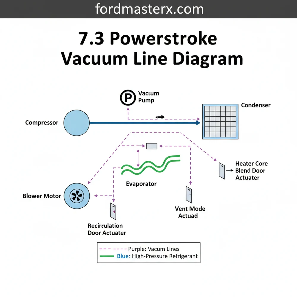
What does the HVAC vacuum diagram show?
This diagram displays the path of vacuum lines from the pump and reservoir into the passenger compartment. It maps how vacuum is distributed to the various actuators that move doors within the HVAC box, allowing the user to select between dash vents, floor vents, and the windshield defrost.
How many vacuum connections are on the 7.3 reservoir?
Typically, the vacuum reservoir tank features two main ports. One port receives vacuum from the electric pump, while the other serves as the output that feeds the main vacuum line through the firewall into the dash. Some models may have an additional T-fitting for the 4WD solenoid system.
What are the symptoms of a bad vacuum line?
The most common symptom is ‘defrost only’ air delivery, where air fails to exit the dash vents. You may also hear a persistent hissing sound under the dash or notice the blower motor is running but the temperature doesn’t change because the compressor or blend doors aren’t engaging.
Can I replace 7.3 vacuum lines myself?
Yes, replacing these vacuum lines is a straightforward DIY task. Most owners use 1/8-inch silicone tubing to replace brittle factory plastic lines. It involves unplugging the old lines and routing the new ones along the same path shown in the diagram, requiring only basic hand tools and patience.
What tools do I need for HVAC vacuum repair?
You will need a handheld vacuum pump or gauge to test for leaks, a pair of needle-nose pliers, and a sharp utility knife for cutting new tubing. If you are also inspecting the condenser or compressor, a manifold gauge set for checking refrigerant levels is highly recommended.


