7.3 Powerstroke Heater Hose Diagram: Complete Layout Guide
A 7.3 Powerstroke heater hose diagram illustrates the routing from the water pump and passenger-side cylinder head to the heater core. It maps out the flow through the heater control valve, ensuring the coolant system configuration provides optimal heat transfer and engine cooling efficiency across the entire diesel engine structure.
📌 Key Takeaways
- Visualizes the routing of coolant between the engine block and the heater core.
- Heater core inlet and outlet hoses are the most critical components to identify.
- Always wait for the engine to cool before inspecting or opening the pressurized system.
- Use the diagram to check for hose collapse or blockage in the heater control valve.
- Use this diagram when diagnosing no-heat issues or identifying mysterious coolant leaks.
Maintaining the cooling system of a heavy-duty diesel engine requires precision and a clear understanding of the coolant flow. If you are a DIY enthusiast or a professional mechanic looking to repair or upgrade your cooling system, this guide provides a comprehensive 7.3 powerstroke heater hose diagram to help you navigate the complex plumbing of this legendary engine. Understanding the routing, connection points, and the role of each component is essential for ensuring your engine stays at its optimal operating temperature while providing reliable cabin heat during cold weather. In this article, you will learn how to identify each hose, the specific tools required for a replacement, and how to troubleshoot common failures using a systematic approach.
Understanding the Heater Hose Layout and Schematic
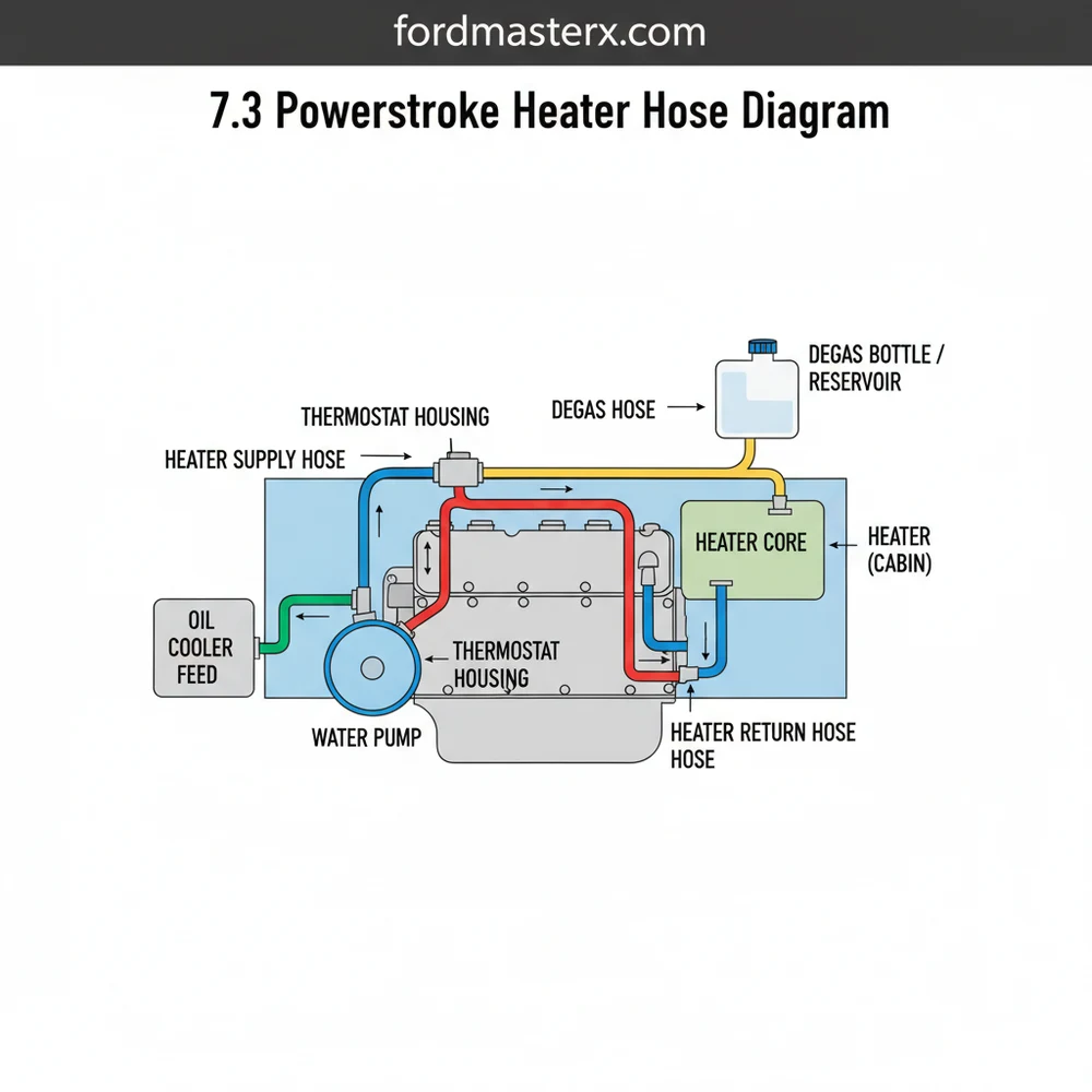
The cooling system of the 7.3 Powerstroke engine is designed for high-capacity heat dissipation. The heater hose system is a secondary loop within this larger configuration that directs hot coolant from the engine block into the heater core located inside the passenger compartment. To accurately read a 7.3 powerstroke heater hose diagram, you must first understand the two primary lines: the supply (inlet) line and the return (outlet) line.
The supply line typically originates from the passenger side of the water pump or the cylinder head. This hose carries the hottest coolant toward the firewall. On most models, this line features a vacuum-operated heater control valve. This specific component is a critical part of the system structure as it regulates the flow of hot coolant into the cabin based on your climate control settings. The return line emerges from the other side of the heater core at the firewall and routes back toward the water pump inlet or the radiator’s lower circuit, completing the loop.
Visually, the layout can appear cluttered due to its proximity to the turbocharger and the large air intake components. However, when looking at a schematic, you will see that the hoses are generally color-coded or labeled to distinguish between high-pressure supply and low-pressure return. The supply hose is often the one connected to the top port of the heater core, while the return is connected to the bottom. This configuration helps prevent air pockets from becoming trapped within the core, which is a common cause of poor heating performance.
|
[Coolant Reservoir] <--(Bypass)-- [Heater Core Outlet] <---(Return Hose)----------+
Visual representation of the component structure and flow direction for the 7.3 Powerstroke cooling loop.
The 7.3 Powerstroke typically utilizes 5/8-inch and 3/4-inch diameter hoses. It is vital to verify the specific size for your supply and return lines, as using the wrong diameter can lead to leaks or restricted flow.
Step-by-Step Guide to Replacing and Interpreting the Diagram

Successfully applying the 7.3 powerstroke heater hose diagram to your vehicle requires a methodical approach. Whether you are performing a routine replacement or a complete system overhaul, following these steps will ensure the job is done correctly and safely.
Required Tools and Materials
- ✓ Hose clamp pliers (constant tension or needle-nose)
- ✓ New heater hoses (specific to 7.3 engine)
- ✓ Replacement heater control valve (if needed)
- ✓ Catch pan and clean coolant (properly rated for diesel engines)
- ✓ Shop towels and degreaser
Never attempt to remove heater hoses while the engine is hot. The cooling system is pressurized and can cause severe burns from escaping steam and boiling coolant.
Implementation Steps
Step 1: Drain the Cooling System
Before disconnecting any components, place a catch pan under the radiator petcock. Drain enough coolant to bring the level below the heater hoses at the firewall. If your coolant is clean and relatively new, you can reuse it; otherwise, this is a perfect time for a fresh fill.
Step 2: Identify Hoses Using the Blueprint
Refer to your 7.3 powerstroke heater hose diagram to locate the supply and return lines. The supply line will have the vacuum control valve integrated into it. Use the diagram to trace these lines from the engine block to the firewall.
Step 3: Remove the Vacuum Line and Clamps
If you are replacing the supply line, carefully disconnect the small vacuum line from the top of the heater control valve. Next, use your hose clamp pliers to compress the tension clamps. Slide the clamps several inches down the hose away from the connection point.
Step 4: Disconnect Hoses from the Firewall
The heater core nipples at the firewall are often made of thin aluminum and can be easily crushed or bent. Do not twist the hose aggressively. If the hose is stuck, use a pick tool or a small flathead screwdriver to gently break the seal between the rubber and the metal before pulling it off.
Step 5: Install the New Configuration
Slide your clamps onto the new hoses before fitting them onto the nipples. Ensure the hoses are routed exactly as shown in the system overview to avoid contact with the exhaust manifold or moving parts like the cooling fan. Reinstall the vacuum line to the heater control valve.
Step 6: Refill and Burp the System
Refill the degas bottle (coolant reservoir) with the appropriate mixture. Start the engine and turn your cabin heater to the highest temperature setting. This opens the control valve and allows coolant to circulate through the core. Monitor the level and add coolant as air pockets are purged from the system.
Common Issues and Troubleshooting Tips

Even with a perfect 7.3 powerstroke heater hose diagram, issues can arise due to the age and operating environment of these trucks. One of the most common problems is a failure of the heater control valve. When this valve fails, it may leak coolant or become stuck in the closed position, resulting in no heat in the cabin. If you notice a sweet smell inside the cab or steam coming from the passenger side of the engine bay, check the connections at the firewall immediately.
Another frequent issue is hose degradation from the inside out. Over time, the rubber can become soft and “mushy” or brittle and cracked. A hose that feels soft when squeezed is likely ready to burst under pressure. Use your schematic to identify any bypass hoses or small coolant lines that may also need attention. If you experience intermittent heat, it could indicate an air lock. Referencing the diagram ensures you have the supply and return lines connected to the correct ports, which is vital for proper air bleeding.
If you are struggling to get the old hoses off the heater core, use a utility knife to carefully slit the hose lengthwise at the connection point. This prevents putting undue stress on the fragile heater core nipples.
Maintenance Best Practices for the 7.3 Powerstroke
To keep your cooling system functioning at peak efficiency, regular maintenance is key. When selecting replacement parts, always opt for heavy-duty silicone hoses or high-quality EPDM rubber. Silicone hoses offer superior heat resistance and longevity, making them a favorite for those who use their trucks for heavy towing.
When performing a repair, inspect the constant tension clamps. While many mechanics prefer traditional worm-gear clamps, the factory spring-style clamps are often better at maintaining a seal as the components expand and contract with temperature changes. If you do use worm-gear clamps, be careful not to overtighten them, as they can cut into the hose material over time.
Additionally, pay close attention to the type of coolant you use. Many 7.3 Powerstroke owners have transitioned to Extended Life Coolant (ELC) to prevent cavitation and scale buildup. Ensure your hoses are compatible with the chemical makeup of your chosen coolant. Regularly checking the routing of your hoses against the original layout will prevent premature wear caused by vibration or rubbing against the engine block. By following this 7.3 powerstroke heater hose diagram and the associated maintenance tips, you can ensure your truck remains reliable for hundreds of thousands of miles. Keeping a printed copy of the schematic in your glovebox is a smart move for any long-distance traveler, allowing for quick identification of components during roadside emergencies.
Frequently Asked Questions
Where is the heater core located?
On a 7.3 Powerstroke, the heater core is located inside the HVAC plenum behind the dashboard on the passenger side. The heater hoses penetrate the firewall to reach it. Identifying this location helps you trace leaks that may cause wet floor mats or a sweet smell inside the cabin.
What does a heater hose diagram show?
This diagram shows the specific layout and routing of the coolant hoses connecting the engine to the heater core. It highlights the flow direction, connections at the water pump, and the placement of the heater control valve, which is essential for maintaining the correct cooling system configuration.
How many heater hoses does the 7.3 Powerstroke have?
The system typically utilizes two primary heater hoses: an inlet hose that carries hot coolant from the engine and an outlet hose that returns it. These hoses are part of a larger structure that includes the water pump and the heater control valve, which regulates the flow.
What are the symptoms of a bad heater hose?
Common symptoms include visible coolant leaks near the firewall, a sweet smell of antifreeze, or an engine that overheats. If the internal hose structure fails, it can collapse, restricting flow and leading to a lack of heat inside the cabin even when the engine is at operating temperature.
Can I replace these heater hoses myself?
Yes, replacing these hoses is a manageable DIY task for most owners. The process involves draining some coolant, loosening the hose clamps at the engine and firewall, and installing new hoses. Using a diagram ensures you maintain the correct routing and secure every component safely during the installation.
What tools do I need for this task?
You will need basic hand tools including pliers for spring-style clamps or a screwdriver for worm-gear clamps. A drain pan is necessary to catch old coolant, and you may need a cooling system pressure tester to verify there are no leaks after you have completed the hose installation.


