7.3 Powerstroke Alternator Wiring Diagram: Easy Setup Guide
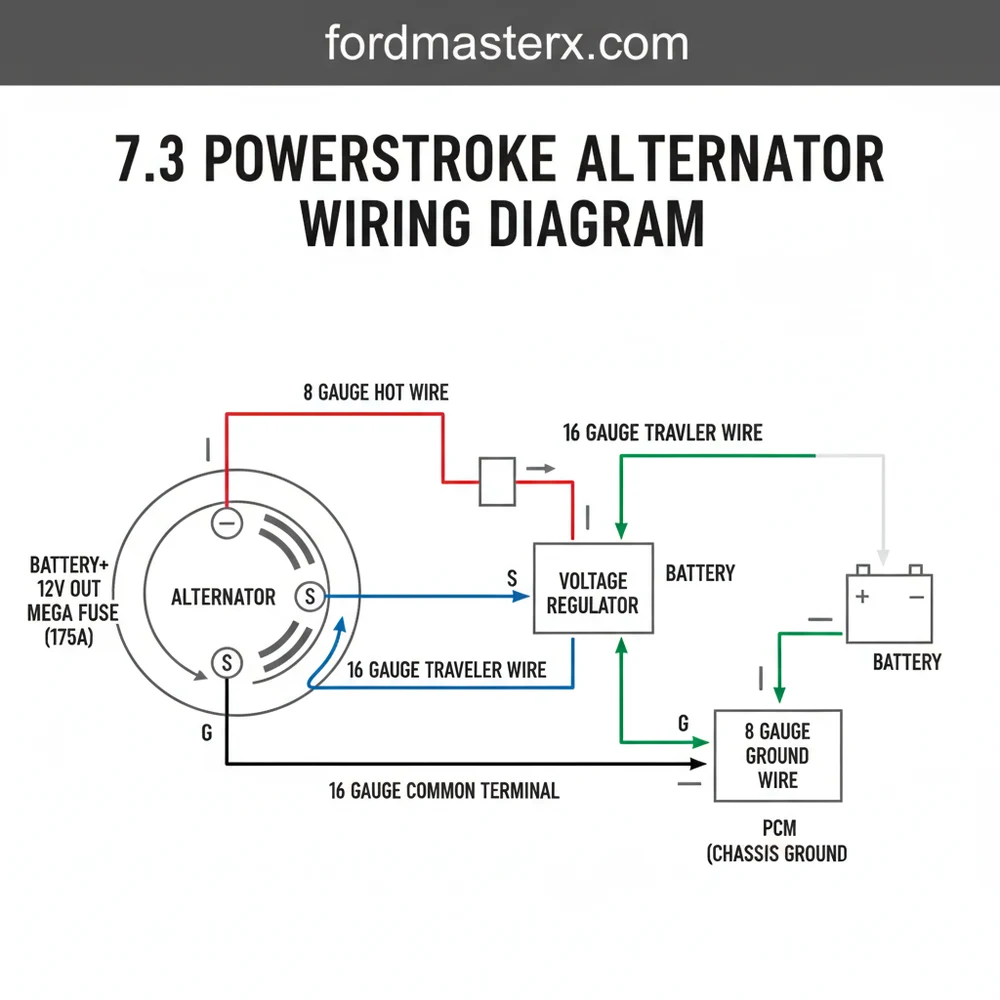
The 7.3 Powerstroke alternator wiring diagram centers on the high-output B+ hot wire and a three-pin regulator plug. It connects the alternator to the dual batteries via a common terminal, while a dedicated ground wire ensures circuit stability. This setup allows the PCM to monitor voltage levels and manage charging efficiency.
📌 Key Takeaways
- The diagram clarifies the path between the alternator and dual-battery system.
- Identifying the three-pin regulator connector is critical for diagnosing charging failure.
- Always disconnect both batteries to prevent accidental shorts during wiring work.
- Clean all contact points at the common terminal to prevent voltage drops.
- Use this diagram when troubleshooting flickering lights or a dashboard battery warning.
When you are working on the legendary Ford 7.3L diesel engine, understanding the 7.3 powerstroke alternator wiring diagram is essential for maintaining a reliable charging system. This heavy-duty engine relies on a dual-battery setup to provide the high cranking amps needed for cold starts and to power the glow plug system. If your charging system fails, you risk being stranded or damaging expensive deep-cycle batteries. Having an accurate wiring schematic allows you to pinpoint whether a charging issue is caused by a blown fuse, a corroded connector, or a failure within the alternator itself. In this guide, you will learn the specific pinouts, wire color codes, and terminal locations required to successfully repair or upgrade your charging system.
The 7.3 Powerstroke typically uses a large-case or small-case internal regulator alternator. While the physical size may vary, the three-pin plug configuration remains largely consistent across the classic Ford diesel production years.
The 7.3 Powerstroke alternator circuit consists of two primary parts: the heavy-gauge output circuit and the three-wire voltage regulation harness. The main output, often referred to as the B+ terminal, is the “hot wire” of the system. This terminal is a threaded stud on the rear of the alternator housing that connects directly to the starter relay or the passenger-side battery via a heavy-duty 6-gauge or 4-gauge wire. This connection is responsible for carrying the high-amperage current needed to recharge the batteries and run the vehicle’s electrical loads.
The secondary component is the three-pin regulator connector. On the 7.3 powerstroke alternator wiring diagram, these wires are labeled as “I,” “S,” and “A.” The “I” terminal (Indicator) is usually a Light Green with Red stripe wire that connects to the instrument cluster’s battery warning light; it acts as the exciter wire to turn the alternator on. The “S” terminal (Stator) is a White with Black stripe wire that loops back into a single-pin connector on the side of the alternator to monitor internal performance. Finally, the “A” terminal (Sensing) is a Yellow with White stripe wire that acts as a “traveler wire” of sorts, running to a constant 12V source to sense the battery’s current state of charge. Understanding these specific connection points is vital for ensuring the internal regulator knows exactly how much voltage to produce at any given time.
Always disconnect both the driver-side and passenger-side negative battery cables before touching the alternator wiring. The main B+ wire is always “hot” and can cause a massive electrical arc if it touches the engine block or chassis.
To interpret and implement the 7.3 powerstroke alternator wiring diagram effectively, follow these sequential steps for installation or troubleshooting:
- ✓ Identify the B+ Output Terminal: Locate the large threaded stud on the back of the alternator. This is your primary hot wire connection. Ensure the terminal is clean and free of oxidation. The nut holding this wire acts similarly to a common terminal in a power distribution block, centering the load.
- ✓ Inspect the Three-Pin Harness: Look at the plastic plug. The Yellow/White wire should show constant battery voltage. If this wire is broken, the alternator will not “know” the battery is low and may fail to charge.
- ✓ Check the Exciter Circuit: Turn the ignition to the “ON” position. Use a multimeter to check the Light Green/Red wire. It should show a small amount of voltage. This signals the alternator to start producing power once the engine is spinning.
- ✓ Verify the Stator Loop: Ensure the short White/Black wire is securely plugged into the single-spade terminal on the alternator housing. This is often overlooked but is critical for the internal regulator’s function.
- ✓ Establish a Solid Ground: Unlike some electrical components that use a dedicated ground wire, the 7.3 alternator is grounded through its mounting brackets to the engine block. Ensure the mounting bolts are tight and the mating surfaces are clean to provide a low-resistance path to the “neutral” or negative side of the system.
- ✓ Test System Voltage: Once connected, start the engine and measure voltage at the battery terminals. A healthy system should read between 13.8V and 14.4V.
For this project, you will need a basic set of tools including a 10mm and 13mm socket for the mounting bolts and terminal nuts, a digital multimeter for checking voltage, and perhaps some wire crimpers if you need to repair a damaged harness. While household wiring might use a brass screw for connections, automotive terminals typically use zinc-plated or copper-clad nuts to withstand the vibrations of a diesel engine. Pay close attention to the gauge of any replacement wires; using a wire that is too thin can lead to overheating and potential fire hazards, especially given the high output of these alternators.
One common issue encountered with the 7.3 Powerstroke is the melting of the three-pin connector. This usually happens due to increased resistance caused by dirt or oil intrusion, leading to heat buildup. If you notice the plastic plug is discolored or brittle, it is best to replace the pigtail entirely rather than attempting to clean it. Another frequent problem is the “Battery” light staying on even when the alternator is new. This is often traced back to a blown fuse in the cabin fuse panel that provides power to the Light Green/Red exciter wire.
If you are experiencing dimming lights at idle, consider the “Big 3” upgrade. This involves replacing the factory B+ wire, the engine block ground wire, and the battery-to-chassis ground wire with 1/0 gauge cabling to reduce voltage drop.
Troubleshooting should always begin at the batteries. Because the 7.3 uses two batteries in parallel, a single dead cell in one battery can “mask” a functional alternator by drawing down all the produced current. If the 7.3 powerstroke alternator wiring diagram shows all connections are correct but voltage remains low, disconnect the batteries and have them load-tested individually. Furthermore, check the “A” terminal (Yellow/White wire) for a blown fusible link. This wire often has a hidden fuse in the wiring loom near the starter relay that can fail if the alternator was previously shorted out.
Maintenance is the key to longevity for any high-amperage electrical system. Regularly check the tension of the serpentine belt; a slipping belt will not only cause a squealing noise but will significantly reduce the alternator’s efficiency. Inspect the mounting bolts periodically, as the vibration of the 7.3L diesel can occasionally loosen them, compromising the ground path. If you are replacing your unit, look for a high-quality 140-amp or 160-amp alternator, which provides better overhead than the stock 110-amp units found on many early models.
When installing a new unit, applying a small amount of dielectric grease to the three-pin connector can help prevent moisture from corroding the pins. Ensure that the main hot wire is routed away from the exhaust manifold to prevent heat damage to the insulation. If you are building a custom setup or an overland rig, following the 7.3 powerstroke alternator wiring diagram ensures that your charging system remains compatible with the factory PCM, allowing the computer to manage the glow plug cycles without interference.
In summary, mastering the 7.3 powerstroke alternator wiring diagram is the best way to ensure your heavy-duty truck remains reliable. By identifying the indicator, stator, and sensing wires, and ensuring a robust B+ connection, you can solve most charging issues in your own driveway. Whether you are dealing with a flickering battery light or a total loss of power, a systematic approach to the wiring harness will save you time and money. Always prioritize high-quality components and thick-gauge wiring to handle the unique demands of the Powerstroke engine, and you will enjoy thousands of miles of trouble-free operation.
Step-by-Step Guide to Understanding the 7.3 Powerstroke Alternator Wiring Diagram: Easy Setup Guide
Identify the main B+ output cable which serves as the primary hot wire for the charging system.
Locate the three-pin regulator plug and inspect the traveler wire signal that triggers the dashboard light.
Understand how the regulator uses a reference signal to maintain voltage at the common terminal.
Connect the ground wire securely to the alternator casing or engine block to ensure a complete circuit.
Verify that the sense wire (acting as a neutral wire reference) is correctly reading battery voltage.
Complete the installation by testing the output with a multimeter to ensure 14.4 volts at high idle.
Frequently Asked Questions
Where is the 7.3 Powerstroke alternator located?
The alternator on a 7.3 Powerstroke engine is conveniently located at the top of the engine on the passenger side. It is mounted to a bracket and driven by the serpentine belt, making it one of the easiest components to access for testing, wiring repairs, or full replacement.
What does the 7.3 alternator wiring diagram show?
The diagram illustrates the electrical flow from the alternator to the batteries and the powertrain control module. It highlights the main power feed, the sense wire for voltage regulation, and the ignition signal wire, helping users identify which wire triggers the charging process and which monitors battery health.
How many wires does the 7.3 Powerstroke alternator have?
Typically, the alternator features one heavy-gauge hot wire connected to the B+ terminal and a three-wire harness plug. These wires include a battery sense wire, an ignition switch signal, and a circuit that connects to the battery indicator light on your dashboard to signal charging system status.
What are the symptoms of a bad 7.3 alternator?
Common symptoms include dimming headlights, a battery light on the instrument cluster, and slow engine cranking. You may also notice the voltmeter on the dash dropping below 13 volts. If the ground wire or common terminal is corroded, the batteries may fail to charge even with a new alternator.
Can I replace the 7.3 alternator wiring myself?
Yes, replacing the alternator or its connector is a straightforward DIY task. By following the wiring diagram, you can splice in a new pigtail or upgrade the main charging wire. Ensure you use heat-shrink connectors to protect the traveler wire and other signals from the harsh diesel engine environment.
What tools do I need for alternator wiring repair?
You will need a basic socket set (specifically 10mm and 13mm), a digital multimeter for testing voltage, wire strippers, and a crimping tool. A wire brush is also essential to clean the ground wire contact points and the common terminal to ensure a secure, low-resistance electrical connection.


