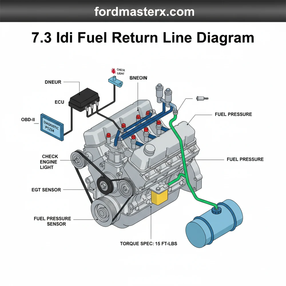
7.3 IDI Fuel Return Line Diagram: Routing Guide
The 7.3 IDI fuel return line diagram illustrates the series of hoses connecting the injector caps back to the fuel tank. This system vents excess fuel and air. Proper routing is vital to prevent hard starts and air intrusion, as this mechanical engine lacks an ECU to monitor return flow electronically.
📌 Key Takeaways
- Provides the visual path for unburned fuel returning to the tank
- Identifies the injector caps as the primary leak points
- Crucial for diagnosing air intrusion and hard-start conditions
- Shows the connection between the filter header and the return circuit
- Essential for DIY replacement of return line kits and O-rings
The 7.3L International Harvester Indirect Injection (IDI) diesel engine is a legendary powerhouse known for its mechanical simplicity and longevity. However, even the most robust engines have an Achilles heel, and for the 7.3 IDI, it is often the fuel return system. Understanding a 7.3 idi fuel return line diagram is essential for any owner or mechanic looking to maintain engine performance and prevent the dreaded “hard start” or “no start” conditions caused by air intrusion. This comprehensive guide provides a detailed breakdown of the return line architecture, offering you the visual and technical clarity needed to identify components, troubleshoot leaks, and perform successful repairs. You will learn how the fuel flows from the injectors back to the tank and how to identify the specific parts that typically fail.
Understanding the 7.3 IDI Fuel Return Line Diagram
The fuel return system on a 7.3 IDI is a “daisy-chain” configuration that links all eight fuel injectors together. Unlike modern common-rail diesels that use high-pressure electronics, the IDI system relies on mechanical pressure and physical pathways to manage excess fuel. When the mechanical injection pump delivers fuel to an injector, not all of it is sprayed into the combustion chamber. The leftover fuel is used to lubricate the injector’s internal needle and must be routed back to the fuel tanks to prevent pressure buildup and heat soak.
A standard 7.3 idi fuel return line diagram illustrates several key components:
- ✓ Injector Caps (Plastic Tees and Elbows): These plastic hats sit atop each injector. They feature two nipples for the “daisy chain” lines, except for the end-of-the-line caps, which may only have one nipple or a plug.
- ✓ O-Rings: Each injector has two small Viton O-rings that provide the seal between the injector body and the plastic cap. These are the most common failure points.
- ✓ Return Hoses: Small-diameter rubber hoses connect the caps in a series. On the 7.3 IDI, these are typically 3/16″ or 1/4″ lines depending on the specific kit used.
- ✓ Crossover Lines: These lines bridge the gap between the driver’s side and passenger’s side cylinder heads, eventually merging at the fuel return manifold or the injection pump’s return fitting.
(Visualizing a top-down view of the engine: The fuel enters the injectors via steel high-pressure lines. The return system begins at the top of each injector, connected by rubber hoses. The lines travel from injector 1 to 3 to 5 to 7 on the passenger side, and 2 to 4 to 6 to 8 on the driver’s side, eventually meeting at the return line header near the back of the engine or the injection pump.)
The diagram also highlights the connection to the fuel filter header. On many 7.3 IDI setups, a small return line also runs from the filter header back to the return circuit. This ensures that any air trapped in the filter is purged back to the tank rather than being forced into the injection pump.
Step-By-Step Guide to Installation and Interpretation

Interpreting the 7.3 idi fuel return line diagram is the first step toward a successful “return kit” installation. Because these engines are purely mechanical, you won’t find an ECU (Engine Control Unit) or an OBD-II port to give you a diagnostic code when the system fails. Instead, you must rely on physical inspection and the diagram to ensure every connection is airtight.
The 7.3 IDI is a “suction” style fuel system in many configurations. If an O-ring on the return line is bad, it might not leak fuel out, but it will let air in while the engine is off. This causes the fuel to drain back to the tank, leaving the lines empty for the next start.
Tools Needed:
- 5/8″ and 3/4″ open-end wrenches (for high-pressure lines)
- Small flathead screwdriver or O-ring pick
- Clean rags and brake cleaner
- Vaseline or clean diesel fuel (for lubrication)
Step 1: Clean the Work Area
Before touching the return lines, clean the area around the injectors thoroughly. Dirt falling into the injector bore can cause catastrophic engine damage. Avoid spraying high-pressure water near the accessory belt or electrical sensors.
Step 2: Remove High-Pressure Lines
Using your wrenches, loosen the steel high-pressure lines at the top of the injectors. You do not always need to remove them entirely from the injection pump, but you must move them enough to pull the plastic return caps off.
Step 3: Remove Old Caps and Hoses
Pull the old plastic caps upward. They may be brittle and break; this is normal for older engines. Remove the old rubber hoses. Note the routing according to your 7.3 idi fuel return line diagram to ensure the new lines follow the same path, avoiding contact with hot exhaust manifolds or the coolant flow pipes.
Step 4: Replace O-Rings
Carefully pick off the two old O-rings on each injector. Inspect the injector body for burrs. Lubricate the new O-rings with a tiny amount of Vaseline or diesel fuel. Slide them on carefully—do not roll them, as this can cause them to twist and leak.
Step 5: Install New Caps and Lines
Press the new plastic caps onto the injectors. You should feel a distinct “click” as they seat over the O-rings. Connect the new hoses between the caps. Ensure you use the provided clamps to secure the hoses. Refer to the diagram to ensure the crossover lines are connected to the correct T-junctions.
Step 6: Reinstall High-Pressure Lines
Thread the steel lines back onto the injectors by hand first to avoid cross-threading. Tighten them to the proper torque spec (usually around 22-25 ft-lbs). Over-tightening can deform the flare and cause a high-pressure leak.
Step 7: Purge the Air
Since the 7.3 IDI has no electric primer, you must crank the engine to move air through. Crack a few of the high-pressure lines at the injector head and crank the engine until fuel spurts out. Tighten the lines and the engine should fire up.
Common Issues and Troubleshooting

The primary issue solved by a 7.3 idi fuel return line diagram is “air intrusion.” Unlike a gasoline engine where a leak triggers a check engine light or a diagnostic code via the OBD-II system, the IDI simply fails to start or runs roughly.
Air in the fuel system can mimic the symptoms of a failing injection pump or worn timing chain (gears). Always check the return lines for air before replacing expensive mechanical components.
Warning Signs of Return Line Failure:
- ✓ The “15-Second Run”: The engine starts perfectly, runs for 15 seconds, and then dies. This indicates the engine burned the fuel in the filter but hit an air pocket in the lines.
- ✓ Damp Injectors: If you see “wet” areas around the base of the plastic caps, the O-rings have failed.
- ✓ Smell of Diesel: Raw fuel smell in the engine bay often points to a cracked return hose or a loose clamp.
If you are experiencing these issues, use the diagram to trace the lines from the rear-most injectors (closest to the firewall) toward the front. Air often enters at the highest point of the system.
Tips and Best Practices for System Maintenance
To keep your 7.3 IDI running reliably, follow these professional tips:
Always use Viton O-rings rather than standard Nitrile. Modern ULSD (Ultra-Low Sulfur Diesel) and biodiesel blends are “dryer” and more corrosive, which can cause standard rubber O-rings to shrink and crack prematurely.
1. Quality Components: When buying a return line kit, avoid the cheapest “no-name” options. High-quality kits include braided hoses that resist swelling and reinforced plastic caps that won’t warp under engine heat.
2. Routing Matters: Ensure your return lines do not touch the glow plug wires or the valve covers. Constant vibration can rub a hole in the rubber hose. Also, keep lines clear of the accessory belt at the front of the engine and the coolant flow hoses to prevent thermal degradation.
3. Torque Specs are Critical: While the return caps are hand-pressed, the high-pressure steel lines require precision. Using a torque wrench ensures you don’t crush the injector pintle or strip the threads on the injection pump.
4. Preventive Replacement: If you are replacing one injector or working on the glow plugs, it is best practice to replace the entire return line kit. Once the seal on an old O-ring is broken, it rarely reseals properly.
5. Monitor Fuel Clarity: If you notice black flecks in your fuel filter during a change, it might be the interior of your return lines deteriorating. Replacing the lines according to the 7.3 idi fuel return line diagram every few years is cheap insurance against a clogged injection pump.
By mastering the layout and function of the fuel return system, you ensure your 7.3 IDI remains one of the most reliable engines on the road. Whether you are dealing with a cold-start issue or performing routine maintenance, a clear understanding of the return flow is your best tool for success.
Step-by-Step Guide to Understanding the 7.3 Idi Fuel Return Line Diagram: Routing Guide
Identify the fuel return path starting from the fuel filter header and the first injector.
Locate the injector return caps sitting on top of each of the eight injectors.
Understand how the hoses daisy-chain from one injector to the next in sequence.
Connect the new O-rings and caps carefully to avoid pinching the seals during installation.
Verify that all hose clamps are positioned correctly and the lines aren’t kinked.
Complete the process by priming the system and checking for leaks during engine operation.
Frequently Asked Questions
Where is the fuel return line located?
On a 7.3 IDI, the return lines are located atop the engine, connecting the plastic caps on each injector. They form a daisy-chain configuration that merges at the back of the engine before heading to the fuel selector valve and back to the fuel tanks.
What does this diagram show?
This diagram displays the flow path of unburned fuel. It starts at the fuel filter header, travels through the injector return caps, and joins a common line. Understanding this flow is crucial because a breach anywhere can cause the engine to lose its prime overnight.
How many connections does the return system have?
The system features eight injector cap connections, several tee-fittings, and a connection to the fuel filter header. Since the 7.3 IDI is purely mechanical, it doesn’t use an OBD-II scanner to find leaks; you must manually inspect these connections for moisture or wetness.
What are the symptoms of a bad return line?
Common symptoms include hard starting after sitting, stalling shortly after startup, and visible fuel dampness around the injectors. Unlike modern trucks, a return leak won’t trigger a check engine light or a diagnostic code, making physical inspection and diagrams essential for troubleshooting.
Can I replace the return lines myself?
Yes, replacing the return lines is a common DIY task. You will need a return line kit containing hoses, caps, and O-rings. Ensure you follow the correct torque spec for any surrounding components you loosen and use plenty of lubricant on the new O-rings.
What tools do I need for this task?
You primarily need a set of basic hand tools, including pliers for the clamps and a small pick to remove old O-rings. Since there is no ECU involved, you won’t need electronic diagnostic tools, just a clean workspace to avoid contaminating the injectors.


