6.7 Powerstroke Wiring Harness Diagram: Easy Setup Guide
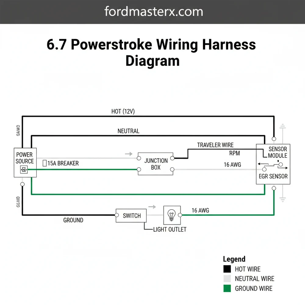
The 6.7 Powerstroke wiring harness diagram maps the electrical pathways between the PCM, injectors, and sensors. It details how the hot wire provides 12V power while the ground wire completes the circuit. This guide helps technicians identify specific pinouts and connector locations to diagnose communication faults or sensor failures efficiently.
📌 Key Takeaways
- Visualizes the 12V DC electrical architecture of the 6.7L engine
- The PCM is the central hub for all harness communication
- Always disconnect batteries before testing high-amperage circuits
- Labeling connectors during removal prevents cross-wiring errors
- Essential for diagnosing intermittent ‘no-start’ or sensor codes
Tracing the electrical intricacies of a high-pressure common-rail diesel engine can feel like navigating a labyrinth without a map. Whether you are dealing with a mysterious crank-no-start condition or performing a full engine swap, having a reliable 6.7 powerstroke wiring harness diagram is the cornerstone of a successful repair. This specialized diagram illustrates the complex relationship between the Power Control Module (PCM), the fuel injection system, and the vast array of sensors that monitor exhaust gas temperatures and boost levels. By understanding how these circuits are laid out, you can pinpoint faults in specific connectors, identify wire color codes, and ensure that every signal reaches its destination with the correct voltage. This guide will walk you through the primary segments of the harness, from the main engine junction to the individual sensor leads, providing you with the clarity needed to master your truck’s electrical system.
Understanding the Core Components of the Harness
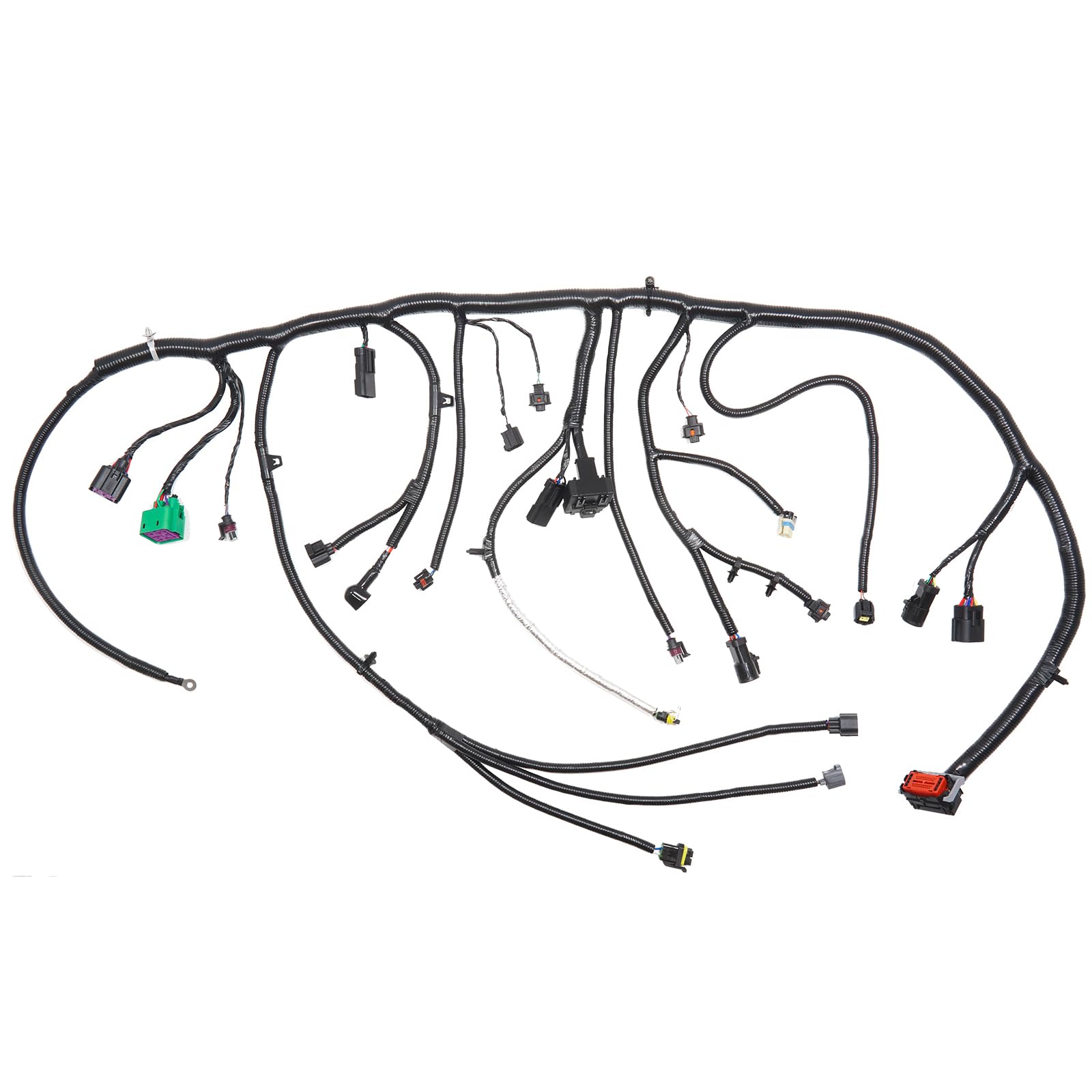
The 6.7 Powerstroke engine utilizes a highly sophisticated electrical architecture designed to handle high heat and constant vibration. The primary diagram for this system is typically divided into several key sections: the engine control side, the chassis side, and the high-voltage injector circuits. At the heart of the layout is the PCM, which acts as the brain of the vehicle. A comprehensive 6.7 powerstroke wiring harness diagram will show multiple large connectors, often labeled as J1 and J2, where hundreds of individual wires converge. These wires are color-coded to prevent cross-connection, though over time, dirt and heat can fade these identifiers, making the diagram’s pinout locations essential for accuracy.
One of the most critical aspects of the diagram is the distinction between signal wires and power delivery. In automotive DC systems, the “hot wire” typically carries a 12-volt battery feed or a 5-volt reference signal provided by the PCM. Conversely, the ground wire serves as the return path to the chassis or the negative terminal of the battery. Unlike residential wiring where you might find a neutral wire, automotive systems rely heavily on a clean chassis ground. However, in complex sensor circuits, a “reference ground” acts similarly to a neutral path, providing a stable baseline for sensor readings. You will also notice “traveler wire” equivalents in the form of CAN-bus communication lines, which carry digital data packets between various control modules rather than simple analog signals.
The 6.7 Powerstroke uses a “floating ground” for certain sensitive sensors to prevent electrical noise from the alternator or starter motor from interfering with delicate data signals. Always refer to the diagram to see if a sensor grounds to the block or directly back to the PCM.
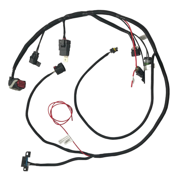
The visual breakdown of the diagram usually features the fuel injector harness as a separate, shielded branch. Because the injectors operate at significantly higher voltages and frequencies than standard lights or accessories, they require a specific gauge of wire to handle the load without overheating. The diagram will also highlight the Glow Plug Control Module (GPCM), which features heavy-duty connections capable of drawing massive amperage during cold starts. Identifying the common terminal points where these high-draw wires meet is vital for diagnosing power distribution issues.
How to Read and Interpret the 6.7 Wiring Diagram
Interpreting a professional-grade wiring diagram requires a systematic approach. It is not merely about following a line from point A to point B; it is about understanding the symbols and the logic of the circuit flow. Follow these steps to effectively use your 6.7 powerstroke wiring harness diagram for diagnostic or installation work.
- ✓ Identify the Legend: Before looking at the wires, check the symbol key. It defines what represents a connector, a splice point, a fuse, or a ground.
- ✓ Locate the Component: Find the specific sensor or actuator you are testing (e.g., the EGT sensor or the Volume Control Valve).
- ✓ Trace the Power Source: Follow the line back to the fuse box or PCM to identify the hot wire and the fuse rating.
- ✓ Check Pin Numbers: Look for the small numbers next to the connector icons; these correspond to the physical pins on the harness plug.
- ✓ Verify Wire Color: Cross-reference the diagram’s color code (e.g., VT-GN for Violet with a Green stripe) with the physical wire in your hand.
To perform these tasks, you will need a few essential tools. A high-quality digital multimeter is non-negotiable for checking voltage and continuity. You should also have a back-probe kit, which allows you to test for signals while the connector is still plugged in, ensuring you are seeing “real-world” data. When checking connections at a common terminal, ensure you are looking for corrosion on any brass screw or metal post, as these are frequent sites for resistance buildup.
Never probe the front of a female connector pin with a thick multimeter lead. This can spread the terminal, leading to a loose connection and intermittent electrical failures. Always use a proper back-probe tool or a thin T-pin.
When you are tracing a circuit, start at the source of power and work your way toward the ground wire. For example, if a sensor is not responding, check for the 5V reference (hot wire) at the connector. If voltage is present, check the ground side for continuity to the chassis. If both are present, the “traveler” or signal wire back to the PCM may be broken or shorted. Understanding the wire gauge is also helpful; thicker wires are generally for power delivery, while thinner wires (high gauge numbers) are reserved for low-current data transmission.
Common Issues and Troubleshooting
The 6.7 Powerstroke engine bay is a harsh environment characterized by extreme thermal cycling. This leads to several common harness failures that a diagram can help you solve. One of the most frequent issues is wire “chafing.” Because the engine vibrates significantly, the wiring harness can rub against metal brackets or the valve covers. This eventually wears through the insulation, causing a hot wire to touch the engine block, resulting in a short circuit and blown fuses.
Another common failure involves the connectors for the Exhaust Gas Temperature (EGT) sensors and the Reductant (DEF) system. These are located under the vehicle and are exposed to road salt, moisture, and debris. A wiring diagram allows you to identify which specific pins are responsible for the sensor signal versus the heater circuit. If you notice erratic voltage readings on your scanner, use the diagram to find the splice points where multiple sensors share a common terminal ground. Corrosion at these splices can cause “phantom” codes where multiple unrelated sensors fail simultaneously.
If you are experiencing multiple sensor codes at once, look for a shared “VREF” (Voltage Reference) line on the diagram. A single shorted sensor can pull down the 5V reference for the entire engine, causing the PCM to lose communication with half a dozen other components.
Warning signs of harness failure include intermittent “limp mode,” flickering dashboard lights, or a sudden loss of power while hitting bumps. If your troubleshooting leads you to a connector, inspect the pins for signs of “green crusties” (copper oxidation). If you find a burnt terminal, it usually indicates high resistance or a loose fitment on the brass screw or tension clip inside the plug.
Tips and Best Practices for Harness Maintenance
Maintaining the integrity of your 6.7 Powerstroke wiring is essential for long-term reliability. One of the best practices is to periodically inspect the plastic loom that protects the wires. Over time, this loom becomes brittle and cracks. Replacing missing sections of loom can prevent the wire gauge from being compromised by heat or abrasion. When making repairs, avoid using “vampire” clips or T-taps; these pierce the insulation and allow moisture to wick into the copper strands, eventually rotting the wire from the inside out.
For any repair, always use marine-grade heat shrink tubing with an internal adhesive. This creates a waterproof seal that protects the connection from the elements. If you are adding aftermarket accessories, like a lift pump or auxiliary lighting, never tap into the PCM harness. Instead, use a dedicated relay and pull power from the battery or a “clean” common terminal in the fuse box to avoid introducing electrical noise into the sensitive engine sensors.
- ✓ Use Dielectric Grease: Apply a small amount to the rubber seals of connectors to keep moisture out, but avoid packing the actual pin holes, as this can trap debris.
- ✓ Verify Grounds: Every few years, remove the main ground wire from the frame, sand the contact point to bare metal, and reattach it.
- ✓ Label Your Work: If you depin a connector for repair, use a small piece of tape to label which wire goes to which hole, cross-referencing your 6.7 powerstroke wiring harness diagram as you go.
Finally, when purchasing replacement parts, always opt for high-quality OEM or reputable aftermarket harnesses. Cheap harnesses often use inferior wire gauge or insulation that cannot withstand the high-temperature environment of a diesel engine. Investing in quality components and following the proper wiring sequence ensures that your Powerstroke remains on the road rather than on a tow truck. By combining a detailed 6.7 powerstroke wiring harness diagram with patient diagnostic techniques, you can confidently handle any electrical challenge your truck presents.
Step-by-Step Guide to Understanding the 6.7 Powerstroke Wiring Harness Diagram: Easy Setup Guide
Identify the primary battery connections and the main fuse block locations.
Locate the heavy-duty ground wire attached to the engine block and frame.
Understand how each hot wire routes power from the relay to the sensors.
Connect the multimeter to check the traveler wire path for signal continuity.
Verify that the return path, often behaving like a neutral wire, is secure.
Complete the process by anchoring the harness to the common terminal brackets.
Frequently Asked Questions
Where is the 6.7 Powerstroke wiring harness located?
The main engine harness is situated primarily in the engine valley and runs along the top of the motor. It connects to the PCM mounted on the passenger-side firewall. Individual branches extend to the fuel injectors, turbocharger, and various sensors located on the cylinder heads and intake manifold.
What does this wiring harness diagram show?
The diagram displays every electrical circuit, including the hot wire power leads and ground wire locations. It provides color-coded wire identification and pin numbers for the PCM connectors. It also identifies how specific sensors relate to the common terminal points for power distribution across the entire engine management system.
How many connections does the harness have?
A 6.7 Powerstroke harness features dozens of critical connections, including eight for injectors and multiple for pressure sensors. Each circuit typically functions as a traveler wire of sorts, carrying signals back to the PCM. The harness also integrates several large bulkheads that manage power flow from the main fuse box.
What are the symptoms of a bad harness?
Common symptoms include random engine stalling, multiple simultaneous sensor fault codes, or a ‘crank but no start’ condition. Physical signs include frayed insulation on a hot wire or corrosion at the connectors. Voltage drops often indicate that a ground wire or neutral wire equivalent is making poor contact.
Can I replace this harness myself?
Replacing the harness is a labor-intensive DIY project requiring several hours and moderate mechanical skill. It involves removing the upper intake and various cooling components to gain access. While no specialized tools are required, meticulous attention to routing is necessary to prevent future heat damage or vibration-induced wire breaks.
What tools do I need for harness troubleshooting?
You will need a high-quality digital multimeter to test continuity and voltage. A basic set of socket wrenches and pliers is required for removal. Additionally, electrical contact cleaner and heat-shrink tubing are useful for repairing minor damage to the protective loom or individual wire segments during the installation process.


