6.7 Powerstroke Vacuum Line Diagram: Easy Reference Guide
The 6.7 Powerstroke vacuum line diagram maps the pneumatic connections from the vacuum pump to the HVAC actuators. This system is vital for controlling air direction through the vents. Vacuum pressure allows the system to switch modes while the blower motor moves air across the evaporator and condenser to manage refrigerant temperatures.
📌 Key Takeaways
- Identifies the routing from the vacuum pump to the HVAC box
- Essential for troubleshooting vents stuck on the defrost setting
- Ensures proper vacuum supply for both 4WD hubs and climate control
- Helps locate the vacuum reservoir and solenoid connections
- Critical for maintaining airflow efficiency across the evaporator
Navigating the complexities of a diesel engine requires precision, especially when dealing with the climate control and auxiliary systems. For owners and mechanics alike, a clear 6.7 powerstroke vacuum line diagram is an essential tool for maintaining vehicle comfort and functionality. Unlike gasoline engines that produce natural manifold vacuum, the 6.7L Powerstroke relies on a dedicated electric vacuum pump to operate critical components, including the HVAC vent actuators and the pulse-controlled wheel ends for four-wheel-drive engagement. Understanding how these lines route from the pump to the air handler is the difference between a quick fix and hours of frustration. This guide will provide a deep dive into the vacuum architecture, identifying key components and offering a systematic approach to troubleshooting and repair.
The vacuum system on a 6.7 Powerstroke is a closed-loop network designed to provide consistent negative pressure to the cabin and drivetrain. The diagram typically begins at the electric vacuum pump, located on the passenger side of the engine compartment, near the battery tray. From here, a primary supply line runs to a vacuum reservoir tank. This tank acts as a buffer, ensuring that even if the pump cycles off, there is enough stored energy to move the HVAC doors. From the reservoir, the lines branch off: one leads toward the firewall to manage the internal air handler, while the other goes toward the vacuum solenoid responsible for the 4×4 hubs.
Within the HVAC portion of the diagram, you will find connections to several vacuum-actuated motors. These motors are responsible for moving the blend doors and mode doors inside the dash. When you adjust your climate settings, you are essentially opening or closing vacuum ports. The diagram also illustrates the relationship between the vacuum system and the larger cooling components. For instance, while the vacuum lines control air direction, the compressor, condenser, and evaporator manage the thermal transfer of the refrigerant. The vacuum lines ensure that the air pushed by the blower motor is directed through the correct heat exchanger—either the heater core for warmth or the evaporator for cooling—before entering the cabin through the supply vents or being pulled back through the return duct.
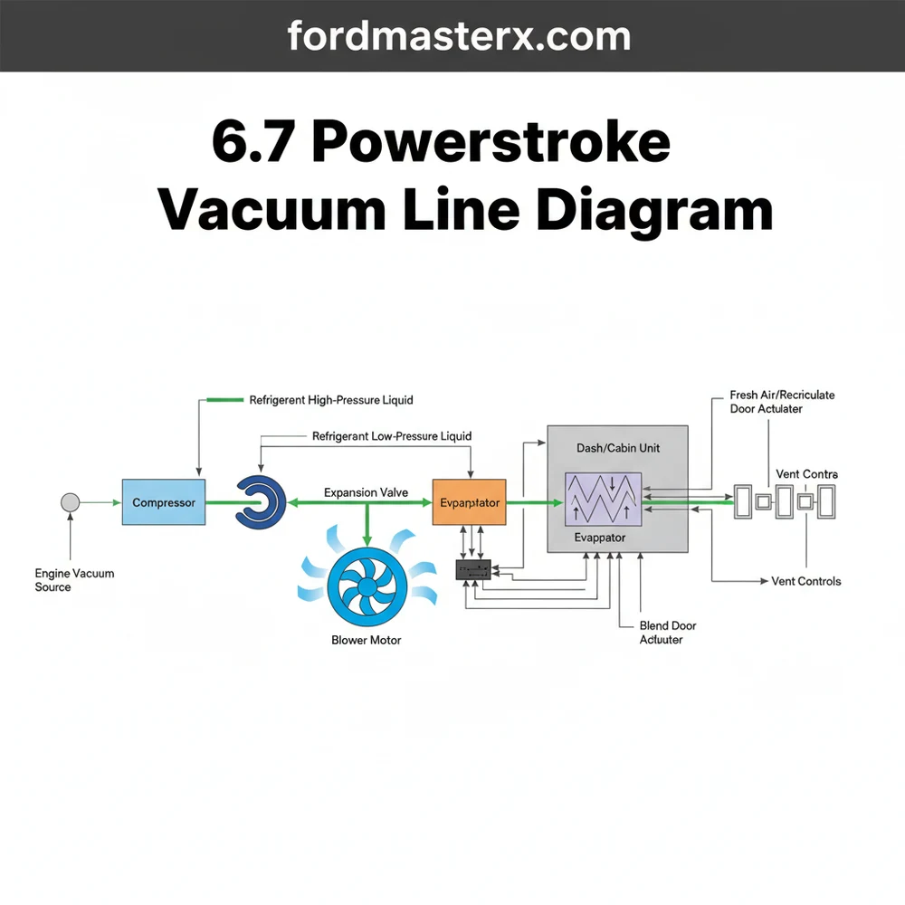
[DIAGRAM_PLACEHOLDER: 6.7 Powerstroke HVAC Vacuum Circuit]
A visual representation showing the Electric Vacuum Pump ➔ Reservoir ➔ Check Valve ➔ Firewall Pass-through ➔ HVAC Mode Actuators. Secondary lines branch to the 4×4 Pulse Solenoid and Wheel Ends.
On the 6.7 Powerstroke, the vacuum pump is electric. If you turn the ignition to the “ON” position without starting the engine, you should hear a faint humming sound for several seconds as the pump primes the vacuum reservoir.
Interpreting a 6.7 powerstroke vacuum line diagram requires a methodical approach. Because vacuum leaks are often microscopic, following the diagram step-by-step is the only way to ensure the integrity of the system.
- ✓ Step 1: Locate the Source – Identify the electric vacuum pump on the passenger side. Ensure the electrical connector is seated and that the pump vibrates when the key is turned on.
- ✓ Step 2: Inspect the Reservoir – Follow the main line from the pump to the plastic reservoir. Check the tank for cracks or impact damage, as these are common points of failure that lead to a total loss of vacuum.
- ✓ Step 3: Test the Check Valve – Between the reservoir and the firewall, there is a small plastic check valve. This valve ensures vacuum only flows in one direction. Remove it and blow through it; air should pass through one way but be blocked the other.
- ✓ Step 4: Trace the Firewall Pass-Through – Look for the thin black nylon line entering the cabin. This line supplies vacuum to the air handler. Ensure it hasn’t been pinched by other engine bay components or melted by exhaust heat.
- ✓ Step 5: Access the Interior Actuators – Inside the cab, behind the glovebox, you can find the primary vacuum manifold. Use the diagram to identify which line goes to the floor, defrost, and dash vents.
- ✓ Step 6: Verify 4×4 Integration – Trace the line leading from the engine bay down to the steering knuckles. Often, a leak in the 4×4 hub seals will “steal” vacuum from the HVAC system, causing the vents to fail when 4WD is engaged.
To perform these steps effectively, you will need a few basic tools: a handheld vacuum pump (such as a Mityvac), a set of needle-nose pliers, and a canister of soapy water to detect leaks.
Never attempt to test vacuum lines while the engine is running and hot. The 6.7 Powerstroke engine bay reaches extreme temperatures, and moving parts like the cooling fan or the compressor pulley can cause serious injury.
The most frequent issue encountered by 6.7 Powerstroke owners is the “Defrost Default” mode. When the vacuum system loses pressure, the HVAC air handler is designed to default to the defrost vents for safety reasons (to ensure the windshield remains clear). If you find that air only blows from the top of the dash regardless of your settings, you have a vacuum leak.
The diagram helps solve this by narrowing down the leak’s location. If the blower motor is pushing air but the compressor isn’t engaging, the issue might be electrical or refrigerant-related rather than vacuum-related. However, if the compressor and condenser are working perfectly but the air comes out the wrong holes, the vacuum line is the culprit. Look for brittle lines near the heat exchanger or any area where the lines transition from rigid nylon to flexible rubber. If the vacuum pump runs continuously without stopping, it is a definitive sign of a large leak in the main supply line or a ruptured diaphragm in an actuator.
If you suspect a leak in the 4×4 system is affecting your HVAC, try capping off the vacuum line that leads to the wheel hubs. If your AC vents start working correctly again, you’ve isolated the problem to the hub seals or their dedicated lines.
To ensure long-term reliability of your HVAC and vacuum systems, maintenance is key. Periodically inspect the vacuum lines for “rot.” Diesel engines produce significant heat and vibration, which can cause rubber connectors to soften and collapse or nylon lines to become brittle and crack. When replacing lines, consider upgrading to high-temp silicone hoses, which withstand engine bay heat much better than factory rubber.
Keep the exterior of the condenser clean. Located at the front of the truck, it is prone to collecting road debris and insects. A clogged condenser forces the compressor to work harder, increasing head pressure and reducing the efficiency of the refrigerant cycle. Similarly, ensure the return duct inside the cabin is not obstructed by floor mats or debris, as this can starve the air handler of air and lead to evaporator icing.
When it comes to components, always choose high-quality replacements. The electric vacuum pump on the 6.7 Powerstroke is a hardworking part; using a cheap after-market version often leads to premature failure and noisy operation. If you are replacing the evaporator or any part of the refrigerant loop, always replace the receiver-drier at the same time to prevent moisture from contaminating the system.
By maintaining a clean 6.7 powerstroke vacuum line diagram and performing regular inspections, you can ensure that your truck remains comfortable in every season. Whether you are hauling a heavy trailer in the summer heat or navigating a blizzard, a healthy vacuum and HVAC system are vital for the performance and safety of your Powerstroke diesel.
Step-by-Step Guide to Understanding the 6.7 Powerstroke Vacuum Line Diagram: Easy Reference Guide
Identify the primary vacuum pump located on the front of the engine block.
Locate the vacuum reservoir and the main supply line entering the firewall.
Understand how the vacuum solenoid directs pressure to the evaporator mode doors.
Connect a vacuum gauge to ensure the compressor and pump maintain steady pressure.
Verify that the blower motor operates at all speeds while switching vent modes.
Complete the inspection by checking for leaks near the condenser and vacuum hubs.
Frequently Asked Questions
Where is the vacuum pump located?
On the 6.7 Powerstroke, the vacuum pump is located on the front of the engine, driven by the serpentine belt. It provides the necessary suction for the HVAC actuators and the brake booster. A failing pump often results in hard brake pedals and HVAC vents that will not switch positions.
What does the 6.7 Powerstroke vacuum line diagram show?
This diagram illustrates the path of vacuum pressure from the pump through the reservoir and into the cabin’s HVAC system. It specifically details how vacuum is routed to different actuators that control air doors, working in tandem with the blower motor and compressor to regulate the cabin temperature effectively.
How many connections does the HVAC vacuum solenoid have?
The HVAC vacuum solenoid typically has two main vacuum ports: one for the vacuum supply from the reservoir and one for the output to the dash actuators. It also features a two-pin electrical connector that allows the truck’s computer to manage vacuum flow based on your selected climate settings.
What are the symptoms of a bad vacuum line?
The most common symptom is air only blowing from the defrost vents, regardless of the setting. You might also notice the 4WD failing to engage or hear a distinct hissing sound under the hood. This occurs when vacuum leaks prevent the doors from redirecting air cooled by the refrigerant.
Can I replace vacuum lines myself?
Yes, replacing vacuum lines is a manageable DIY project for most owners. The lines are generally accessible in the engine bay and behind the glove box. Using a 6.7 Powerstroke vacuum line diagram makes it easy to identify which brittle plastic lines need to be swapped for durable silicone tubing.
What tools do I need for vacuum line repair?
You will need a vacuum pressure gauge to test for leaks and verify pump output. Needle-nose pliers are helpful for removing old hoses from plastic barbs. Additionally, keep some various-sized T-fittings and a sharp utility knife on hand to cut and join new sections of vacuum hose properly.