6.7 Powerstroke Fuel Line Diagram: Complete Routing Guide
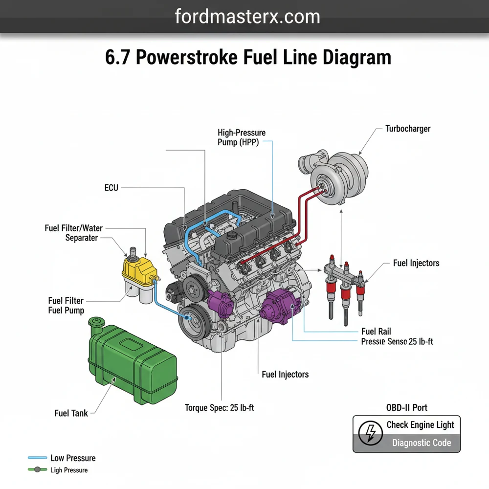
A 6.7 Powerstroke fuel line diagram illustrates the flow from the lift pump to the DFCM, then to the high-pressure CP4 pump and common rails. It identifies the supply and return lines, fuel filters, and injector connections, making it essential for diagnosing pressure drops or replacing damaged lines safely.
📌 Key Takeaways
- Main purpose of this diagram is to trace fuel from the tank to the injectors
- Most important components to identify are the CP4 pump and high-pressure rails
- Safety consideration: always relieve system pressure before opening lines
- Practical application: use the diagram to find air intrusion points or leaks
- Use this diagram during filter changes or when diagnosing low pressure codes
Understanding the complex layout of a modern diesel engine requires more than just mechanical intuition; it demands a clear and accurate 6.7 powerstroke fuel line diagram. Whether you are dealing with a stubborn leak, performing a routine fuel filter change, or upgrading the High-Pressure Fuel Pump (HPFP), knowing exactly where each line originates and terminates is crucial for maintaining engine performance and longevity. This guide provides a detailed breakdown of the fuel delivery system, from the tank to the piezo-electric injectors, ensuring you can navigate the intricacies of the Bosch CP4 system and the low-pressure supply lines with confidence. By the end of this article, you will be equipped to identify every major fuel component and understand how they interact with the vehicle’s electronic control systems.
The 6.7L Powerstroke utilizes a high-pressure common rail fuel system. This system is divided into two distinct sides: the low-pressure side (suction and lift) and the high-pressure side (injection). Understanding the transition point between these two is vital for safety and effective diagnostics.
The 6.7 powerstroke fuel line diagram represents a sophisticated loop that ensures clean, pressurized fuel reaches the combustion chamber while excess fuel is returned to the tank for cooling and filtration. The diagram typically begins at the fuel tank, where the primary lift pump—often housed within the Diesel Fuel Conditioning Module (DFCM)—pulls fuel through a suction line. From the DFCM, the fuel is pushed forward through a supply line to the secondary fuel filter located under the hood.
A visual breakdown of the diagram components includes:
- ✓ Primary Fuel Filter/Water Separator (DFCM): Located on the frame rail, this is the first line of defense against contaminants.
- ✓ Secondary Fuel Filter: Situated in the engine bay, this filter captures microscopic particles before the fuel enters the high-pressure pump.
- ✓ Bosch CP4.2 High-Pressure Pump: Driven by the engine’s internal gearing, this pump compresses fuel to extreme pressures, often exceeding 29,000 PSI.
- ✓ High-Pressure Fuel Rails: Two rails (one for each bank) act as accumulators, holding pressurized fuel ready for the injectors.
- ✓ Fuel Return Lines: These lines carry hot, unused fuel back from the injectors and the CP4 pump through a fuel cooler and finally back to the tank.
In most 6.7 powerstroke fuel line diagrams, color coding is used to differentiate between the low-pressure supply (often blue or green), the high-pressure injection lines (red or solid black), and the return lines (yellow or orange). It is important to note that while the core architecture remains consistent across various truck models, slight variations in line routing may exist depending on the chassis configuration, such as whether the vehicle is a standard pickup or a chassis cab with dual fuel tanks.
Interactive 6.7 Powerstroke Fuel System Layout: Component Locations and Flow Direction
Interpreting a fuel line diagram and applying it to a physical repair requires a systematic approach. The complexity of the 6.7L engine means that many fuel lines are tucked away beneath other components, such as the upper intake manifold or the accessory belt area.
High-pressure fuel systems retain pressure even after the engine is turned off. Never loosen high-pressure fittings while the engine is running or immediately after shutdown. Residual pressure can cause fuel to penetrate the skin, leading to severe injury or death.
Follow these steps to effectively use the 6.7 powerstroke fuel line diagram for inspection or component replacement:
1. Safety and Preparation: Before starting, disconnect the batteries. Ensure you have clean, lint-free rags and caps for the fuel lines. Diesel fuel systems are extremely sensitive to debris; even a single speck of dust can damage the high-pressure pump or clog an injector.
2. Identify the Source of the Leak or Issue: Use the diagram to trace the flow. If you have a low-pressure fault, focus on the lines between the tank and the CP4 pump. If the issue is high-pressure related, inspect the lines between the CP4 pump, the rails, and the injectors.
3. Accessing the Components: Many fuel lines require the removal of the upper intake manifold. Use the diagram to identify which lines are “hard lines” (steel) and which are “soft lines” (rubber/nylon). Note that the accessory belt and fan shroud may need to be cleared to access the front of the CP4 pump.
4. Depressurizing the System: While the system usually bleeds down over time, it is best practice to use an OBD-II diagnostic tool to monitor the fuel rail pressure (FRP) before cracking any lines. Once the pressure is confirmed to be at a safe level, slowly loosen the fittings.
5. Proper Disconnection: Most low-pressure lines on the 6.7 Powerstroke use quick-connect fittings. Use the appropriate disconnect tool to avoid damaging the plastic tabs. High-pressure lines utilize threaded flare nuts that require a flare nut wrench (Crowsfoot) to prevent rounding the edges.
6. Replacement and Alignment: When installing new lines, refer to the diagram to ensure proper routing. Lines must not rub against the timing chain cover or other vibrating components. Use the following torque spec for high-pressure line nuts: generally 30-35 lb-ft (always verify with your specific service manual).
7. Priming the System: After the lines are reinstalled, the system will contain air. Do not crank the engine immediately. Cycle the ignition to the “On” position (without starting) for 30 seconds. Repeat this process 6-10 times. This allows the lift pump in the DFCM to purge air through the return lines back to the tank.
8. Leak Testing: Once primed, start the engine and perform a visual inspection. Check all connection points identified in your 6.7 powerstroke fuel line diagram for signs of moisture.
When replacing fuel lines, always replace the O-rings and gaskets associated with the fittings. Reusing old seals in a high-pressure diesel system is a common cause of “comeback” leaks.
When problems arise, the ECU (Engine Control Unit) will often trigger a check engine light. Using an OBD-II scanner is the most efficient way to correlate physical symptoms with system failures. Common issues include the P0087 (Fuel Rail Pressure Too Low) or P0088 (Fuel Rail Pressure Too High) diagnostic code.
If your 6.7 powerstroke fuel line diagram shows a drop in pressure across the filters, it is a sign of clogging. However, if the ECU detects erratic pressure, the issue may lie with the Volume Control Valve (VCV) on the CP4 pump or the Pressure Control Valve (PCV) on the fuel rail. Air intrusion is another frequent problem; if you see bubbles in the clear test lines or hear a whining noise from the DFCM, check the suction line from the tank for cracks.
Persistent check engine light issues related to fuel may also be linked to the fuel cooling system. Some 6.7 models utilize a fuel cooler that integrates with the secondary coolant flow loop. If this cooler fails, fuel temperatures can rise, leading to decreased density and potential pump cavitation.
To keep your 6.7 Powerstroke running smoothly, maintenance of the fuel delivery system is non-negotiable. The high-pressure pump relies entirely on the lubricity of the diesel fuel itself. Poor quality fuel or the presence of water can lead to “internal pump grenading,” which sends metal shavings through the entire fuel line diagram, destroying injectors and requiring a multi-thousand dollar repair.
- ✓ Drain the Water Separator: Do this monthly or whenever the “Water in Fuel” light appears on the dash.
- ✓ Use High-Quality Filters: Only use OEM (Motorcraft) filters. Aftermarket filters often lack the proper micron rating or water-shedding capabilities.
- ✓ Fuel Additives: Consider using a lubricity-enhancing additive at every fill-up to protect the CP4 pump.
- ✓ CP4 Disaster Prevention Kit: For long-term reliability, many owners install a “disaster kit.” This modifies the fuel line routing so that if the pump fails, contaminated fuel is sent back to the tank/filters rather than directly into the expensive injectors.
In summary, the 6.7 powerstroke fuel line diagram is more than just a map; it is an essential diagnostic tool for any owner or technician. By understanding the flow from the lift pump through the high-pressure rails and back through the return system, you can effectively troubleshoot performance issues, replace components safely, and perform the necessary maintenance to keep your truck on the road. Always prioritize cleanliness and follow the specific torque specs to ensure the high-pressure system remains sealed and reliable for miles to come.
Step-by-Step Guide to Understanding the 6.7 Powerstroke Fuel Line Diagram: Complete Routing Guide
Identify the supply and return lines starting from the fuel tank.
Locate the Diesel Fuel Conditioning Module (DFCM) on the frame rail.
Understand how the secondary filter feeds the CP4 high-pressure pump.
Connect the high-pressure lines from the pump to the fuel rails.
Verify that all connections meet the manufacturer’s torque spec exactly.
Complete the process by priming the system to remove trapped air.
Frequently Asked Questions
Where is the primary fuel filter located?
The primary fuel filter is located inside the Diesel Fuel Conditioning Module (DFCM) mounted on the driver-side frame rail. It sits between the fuel tank and the engine, serving as the first line of defense against contaminants and water before the fuel reaches the engine-mounted secondary filter.
What does the fuel line diagram show?
This diagram illustrates the path of diesel fuel from the tank through the lift pump, conditioning module, and secondary filter. It highlights the high-pressure lines connecting the CP4 pump to the fuel rails and injectors, as well as the return lines that send excess fuel back to the tank.
How many fuel lines connect to the secondary filter?
The engine-mounted secondary fuel filter typically features four connections. These include the main supply line from the DFCM, the outlet to the high-pressure pump, and two return lines that manage overflow and air bleed-off. Ensuring these are seated correctly is vital to prevent air from entering the system.
What are the symptoms of a bad fuel line?
Symptoms include a visible leak, a persistent check engine light, or a specific diagnostic code like P0087. You may notice hard starting, engine stutters, or a loss of power. Using an OBD-II scanner can help confirm if the ECU is detecting low fuel rail pressure.
Can I replace these fuel lines myself?
Replacing low-pressure lines is manageable for DIYers, but high-pressure lines require extreme caution. You must follow the exact torque spec for every fitting to prevent leaks. If the system is opened, you must perform the priming procedure to purge air before attempting to start the engine.
What tools do I need for fuel line repair?
You will need a set of flare nut wrenches, a fuel line disconnect tool kit, and a high-quality torque wrench. Additionally, an OBD-II scan tool is necessary to monitor live pressure data from the ECU and clear any diagnostic code triggered by a leak or pressure drop.