6.7 Powerstroke Engine Diagram: Complete Layout Guide
A 6.7 Powerstroke engine diagram displays the layout of the V8 diesel engine, highlighting the high-pressure fuel system, twin-pilot injectors, and turbocharger placement. It provides a visual roadmap for locating sensors and structural components, essential for performing maintenance or addressing a check engine light on Ford Super Duty trucks.
📌 Key Takeaways
- Provides a visual map for navigating the complex Ford diesel engine architecture
- Highlights the relationship between the high-pressure fuel system and the ECU
- Essential for locating sensors when a check engine light appears on the dash
- Always refer to the diagram to ensure every torque spec is met during reassembly
- Best used during routine maintenance like filter changes or complex sensor diagnostics
Navigating the complexities of a modern diesel powerhouse requires precision, which is why a detailed 6.7 l 6.7 powerstroke engine diagram is an essential tool for any truck owner or technician. Whether you are performing routine maintenance or tackling a major repair, understanding the layout of the “Scorpion” engine architecture ensures you can locate critical components quickly and accurately. This guide provides a comprehensive breakdown of the engine’s internal and external systems, covering everything from the high-pressure fuel system to complex cooling circuits. By the end of this article, you will be equipped to interpret technical schematics, diagnose issues using diagnostic codes, and perform repairs with professional confidence.
Decoding the 6.7L Powerstroke Engine Diagram
The 6.7-liter Powerstroke engine, often referred to by its code name “Scorpion,” features a revolutionary design that differs significantly from its predecessors. When viewing a comprehensive 6.7 l 6.7 powerstroke engine diagram, the first thing you will notice is the unique reverse-flow cylinder head layout. In this configuration, the exhaust manifolds are located in the engine’s “valley” (the space between the cylinder banks), while the intake remains on the outside. This design allows for a more compact engine footprint and positions the turbocharger directly above the exhaust ports for near-instantaneous boost response.
A standard diagram identifies several primary zones. At the front, you will see the complex accessory belt drive system, which powers the alternator, water pump, and air conditioning compressor. Deep within the block, the timing chain assembly is depicted, which is responsible for synchronizing the crankshaft and camshaft movement. Unlike older pushrod engines, the 6.7L uses a high-precision chain to maintain timing under extreme torque loads. The diagram also highlights the dual cooling systems: one high-temperature circuit for the engine block and one low-temperature circuit for the charge air cooler and transmission oil cooler.
The 6.7L Powerstroke utilizes a Bosch CP4.2 high-pressure fuel pump located at the front of the engine valley. This component is critical for generating the massive pressure required for common-rail injection and is a frequent point of reference in fuel system diagrams.
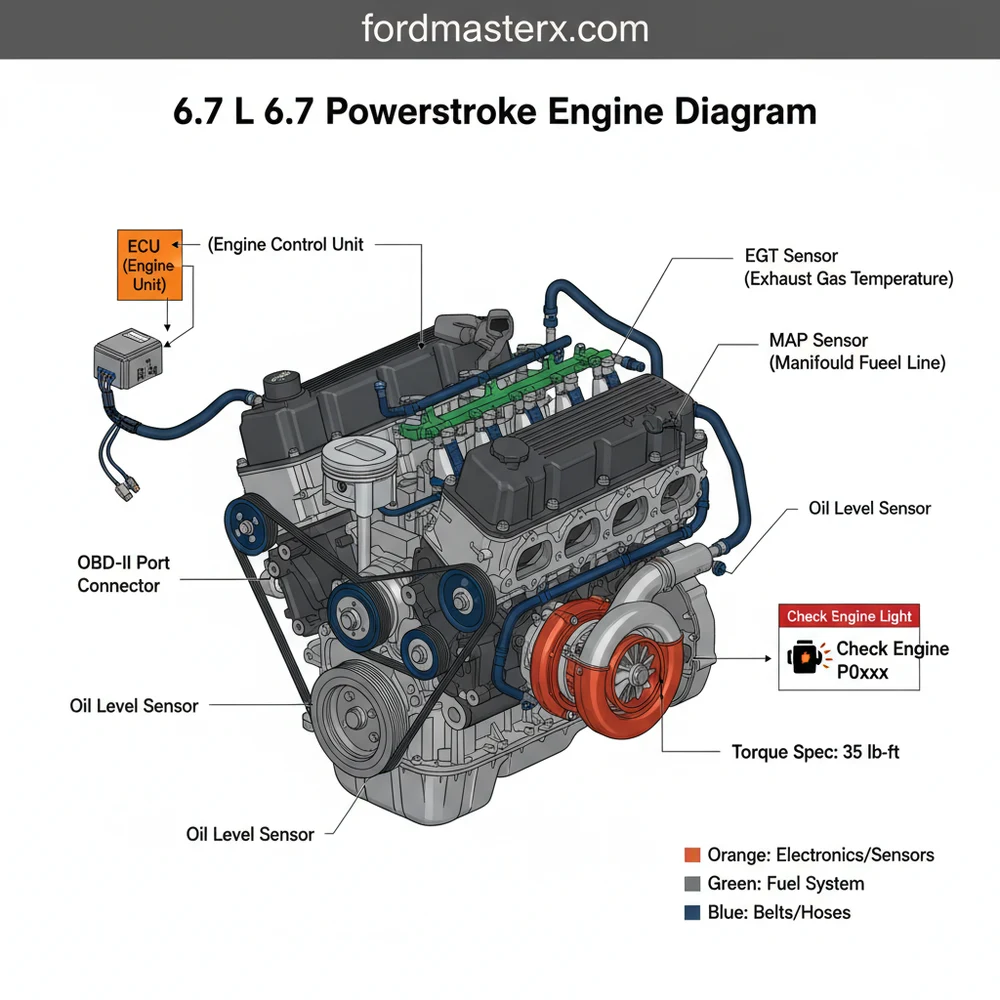
The electrical side of the diagram is equally vital. It maps out the connection between the ECU (Engine Control Unit) and the various sensors, such as the Mass Air Flow (MAF) and Manifold Absolute Pressure (MAP) sensors. This electronic brain monitors every aspect of combustion to maximize efficiency and minimize emissions, communicating through the OBD-II port located under the dashboard.
[DIAGRAM_PLACEHOLDER: 6.7L Powerstroke Engine Component Map showing Turbocharger, CP4 Pump, Reverse Flow Heads, and Cooling Circuits]
Step-By-Step Guide to Reading and Using the Diagram

Interpreting a technical engine schematic can be daunting for beginners. However, by breaking the process down into logical steps, you can use the 6.7 l 6.7 powerstroke engine diagram to navigate the engine bay like a pro. Follow these steps to translate the diagram into real-world mechanical action.
Step 1: Orient Yourself to the “Valley”
Start by identifying the center of the engine. In the 6.7L Powerstroke, the turbocharger sits in the “V” of the engine. Use your diagram to locate the exhaust inlets entering the turbo from the center and the intake charge pipes exiting toward the outer edges of the cylinder heads. This is the opposite of almost every other V8 engine you may have worked on.
Step 2: Trace the Accessory Belt Path
Locate the accessory belt routing on your diagram. This is usually shown as a separate sub-diagram. Note the tensioner location and the direction the belt wraps around the pulleys. If you are replacing the belt, use the diagram to ensure the ribbed side and flat side of the belt are contacting the correct pulleys.
Step 3: Understand the Coolant Flow
The 6.7L has two separate radiators. Use the coolant flow diagram to distinguish between the primary circuit (which keeps the engine at operating temperature) and the secondary circuit (which cools the intercooler). This is vital if you are troubleshooting an overheating issue, as you must know which reservoir and pump belong to which system.
Step 4: Locate the Diagnostic Interfaces
Find the ECU on the diagram, typically mounted on the passenger-side firewall or near the battery tray. Follow the wiring harness representation to the OBD-II port location. This path is essential when you need to plug in a scanner to read a diagnostic code or monitor live engine data during a test drive.
Step 5: Reference the Torque Specs
Never perform a repair without checking the torque spec for each bolt. A high-quality diagram will often include a table listing the specific foot-pounds or inch-pounds required for critical fasteners like the fuel injector hold-downs, intake manifold bolts, and valve cover screws. Using a calibrated torque wrench according to the diagram’s specifications prevents snapped bolts and vacuum leaks.
The fuel system on the 6.7L Powerstroke operates at pressures exceeding 29,000 PSI. Never loosen fuel lines while the engine is running or immediately after shutdown. Consult the diagram to identify bleed-off points and safety valves before servicing.
Step 6: Identify Sensor Locations
When a check engine light appears, use the diagram to find the specific sensor mentioned by your scan tool. For example, if you receive a code for the Exhaust Gas Temperature (EGT) sensor, the diagram will show you exactly which of the four sensors in the exhaust stream needs to be inspected or replaced.
Common Issues and Troubleshooting with Diagrams
Even the most reliable engines face challenges over time. The 6.7L Powerstroke is known for specific issues where a 6.7 l 6.7 powerstroke engine diagram becomes an invaluable diagnostic partner. One frequent problem is the failure of the CP4.2 high-pressure fuel pump, which can send metal debris through the entire fuel system. By referencing the fuel system schematic, you can identify the bypass points and determine if the contamination has reached the injectors.
Another common concern is the check engine light triggered by emissions components. The EGR (Exhaust Gas Recirculation) cooler can become clogged with carbon over time. The diagram helps you locate the EGR assembly tucked behind the intake, allowing you to check for leaks or blockages. Furthermore, if you encounter a diagnostic code related to boost pressure, the diagram guides you through the complex vacuum lines and electronic actuators that control the Variable Geometry Turbocharger (VGT).
- ✓ P0401: Insufficient EGR Flow – Locate the EGR valve and cooler on the diagram.
- ✓ P0087: Fuel Rail Pressure Too Low – Trace the lines from the tank to the high-pressure pump.
- ✓ P0299: Turbo Underboost – Inspect the VGT actuator and charge air cooler hoses.
Tips and Best Practices for Maintenance
Maintaining a 6.7L Powerstroke is a long-term investment in your vehicle’s longevity. To keep your engine running smoothly, always follow a strict maintenance schedule informed by your engine’s specific requirements. One of the most important practices is using high-quality, OEM-grade fuel filters. Because the fuel system is so sensitive to particulates, changing both the primary and secondary fuel filters every 15,000 to 22,500 miles is non-negotiable.
When checking coolant flow, always test the nitrite levels and the pH of the coolant in both reservoirs. The 6.7L engine requires specific additives to prevent cavitation and corrosion in the cooling jackets.
When performing any work involving the accessory belt, take the opportunity to spin the pulleys by hand to check for bearing wear. If you hear a grinding noise or feel play in the water pump or idler pulley, replace it immediately to prevent a roadside breakdown. Additionally, keep a log of every diagnostic code that appears, even if it clears itself. This history can help you identify a failing ECU or a loose ground wire before it causes a major electrical failure.
Finally, always ensure that any replacement hardware meets the original torque spec. Diesel engines vibrate significantly, and a bolt that is under-torqued can vibrate loose, while an over-torqued bolt can fail under the heat cycles of the engine. By consistently referencing your 6.7 l 6.7 powerstroke engine diagram and adhering to these best practices, you ensure that your truck remains a reliable workhorse for hundreds of thousands of miles.
In conclusion, having a firm grasp of the 6.7 l 6.7 powerstroke engine diagram is the difference between a frustrating afternoon in the garage and a successful, precision-executed repair. From understanding the coolant flow to interpreting OBD-II data, this knowledge empowers you to maintain one of the most capable diesel engines ever produced.
Step-by-Step Guide to Understanding the 6.7 Powerstroke Engine Diagram: Complete Layout Guide
Identify the main engine block and cylinder head orientations to establish a reference point.
Locate the turbocharger assembly positioned in the ‘valley’ of the engine for easy identification.
Understand how the secondary cooling system maintains temperature for the intercooler and fuel system.
Connect the location of various sensors back to the ECU using the wiring path layout.
Verify that the high-pressure fuel lines and rails are mapped correctly before attempting any disassembly.
Complete the process by cross-referencing your physical engine components with the diagram to ensure accuracy.
Frequently Asked Questions
Where is the ECU located?
The ECU is typically located on the driver’s side firewall within the engine compartment. It is encased in a rigid housing to protect sensitive electronics from heat and moisture. Identifying this unit is the first step when scanning for a diagnostic code or troubleshooting electrical communication errors.
What does the 6.7 Powerstroke engine diagram show?
This diagram provides a detailed architectural map of the engine, including the turbocharger, cooling systems, and fuel delivery components. It helps users visualize how various systems interconnect, making it easier to locate specific sensors or mechanical parts that require inspection or replacement during a repair project.
How many fuel injectors does this engine have?
The 6.7 Powerstroke utilizes eight high-pressure common rail injectors, one for each cylinder. These injectors are controlled by the engine computer to provide precise timing. When replacing them, it is critical to follow the exact torque spec for the hold-down bolts to prevent leaks or combustion issues.
What are the symptoms of a bad turbocharger?
A failing turbocharger usually causes a noticeable loss of power, excessive smoke from the tailpipe, and may trigger a check engine light. You might also hear an unusual whining sound. Using a diagram helps you locate the actuator and oil lines to check for leaks or physical damage.
Can I replace the sensors myself?
Many sensors on the 6.7 Powerstroke are accessible for DIY replacement. Using the engine diagram to find the exact location of the EGT or MAP sensors simplifies the process. However, you will need an OBD-II scanner to clear any remaining codes from the system after the physical replacement.
What tools do I need for diagnostics?
For basic diagnostics, an OBD-II scan tool is essential to read any stored diagnostic code. For mechanical work, you will need a complete socket set, extensions for hard-to-reach areas, and a calibrated torque wrench to ensure all fasteners are tightened correctly according to factory specifications.


