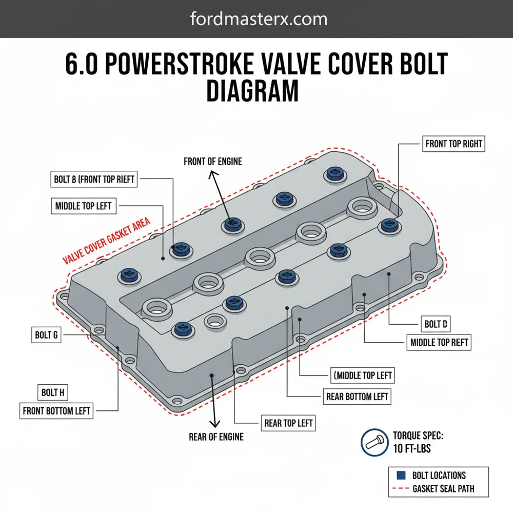
6.0 Powerstroke Valve Cover Bolt Diagram: Layout Guide
The 6.0 powerstroke valve cover bolt diagram illustrates the specific layout of the mounting hardware across the cylinder head. These bolts secure the structure of the cover to prevent oil leaks within the high-pressure system. Proper identification of each component ensures uniform pressure across the gasket for a reliable configuration.
📌 Key Takeaways
- Identifies the specific bolt locations for the 6.0L cylinder head
- Helps prevent uneven torque and potential oil leaks
- Essential for DIY mechanics performing injector or glow plug service
- Distinguishes between standard bolts and those with studs for brackets
- Use this diagram during reassembly to ensure structural integrity
The 6.0L Powerstroke diesel engine, found in Ford Super Duty trucks from 2003 to 2007, is a powerhouse known for both its impressive performance and its demanding maintenance schedule. For the DIY enthusiast, one of the most common tasks involves removing the valve covers to access the fuel injectors, glow plugs, or the high-pressure oil system components like standpipes and dummy plugs. Understanding the valve cover bolt diagram, torque sequence, and specific hardware requirements is essential to prevent oil leaks and ensure the longevity of the engine’s top end. This guide provides a comprehensive look at the 6.0 Powerstroke valve cover bolt configuration and the practical steps needed to master this repair.
Main Components and Hardware Features
The 6.0 Powerstroke utilizes two distinct valve covers—one for the driver-side (left) bank and one for the passenger-side (right) bank. While the bolt patterns are mirror images of each other, the obstacles surrounding them differ significantly. Each valve cover is held in place by 10 individual bolts. These are not standard hardware store bolts; they are specialized M6 x 1.0 threaded fasteners designed with integrated spacers to prevent over-compression of the valve cover gasket.
Key Specifications:
- Bolt Quantity: 10 bolts per side (20 total for the engine).
- Socket Size: Typically a 10mm or 12mm deep socket is required, though some aftermarket bolts may vary.
- Material: Steel bolts with rubber-encapsulated washers to provide a secondary seal against oil seepage.
- Gasket Type: Reusable silicone-over-carrier gaskets (though replacement is highly recommended if they show signs of flattening or cracking).
The driver-side valve cover is notably obscured by the Fuel Injection Control Module (FICM) and its complex wiring harness. The passenger-side cover is often more difficult to access due to its proximity to the HVAC (heater core) housing and the evaporator case. Understanding the layout before you begin is the difference between a two-hour job and an all-day ordeal.
How to Read the Bolt Diagram and Torque Sequence

When looking at the 6.0 Powerstroke valve cover from above, the bolts are arranged in a rectangular perimeter. While the Ford service manual does not mandate a hyper-specific “star pattern” as strictly as it does for cylinder heads, following a structured sequence is vital to ensure the gasket seats evenly. Uneven pressure can lead to “weeping” leaks that are difficult to fix once the engine is fully reassembled.
The Bolt Layout:
Imagine the valve cover as a grid. There are four bolts along the top (intake manifold side), four bolts along the bottom (exhaust manifold side), and one bolt on each of the short ends (front and back). To properly seal the cover, you should start from the center and work your way outward.
- Inner Center Pair: Start with the two bolts located in the middle of the long runs (top and bottom center).
- Outer Center Pair: Move to the next set of bolts flanking the center.
- Ends: Tighten the bolts on the far front and far rear of the cover.
- Corners: Finally, secure the four corner bolts.
Torque Measurements:
Precision is critical here. The torque specification for 6.0 Powerstroke valve cover bolts is 96 lb-in (96 inch-pounds). It is a common mistake to use a foot-pound wrench and accidentally snap the small M6 bolts. 96 lb-in converts to exactly 8 lb-ft (8 foot-pounds), which is barely more than finger-tight plus a quarter turn. Always use a calibrated inch-pound torque wrench for this task.
Step-by-Step Installation Tips

Working on a 6.0 Powerstroke requires patience, especially regarding the wiring harness. The plastic clips on the injector harness become extremely brittle over time due to engine heat. Here is how to navigate the installation process efficiently:
1. Harness Management: On the driver’s side, you must disconnect the three large FICM plugs. These have squeeze-tabs that often break. Use a small flathead screwdriver to gently assist the tabs. Move the harness as far toward the battery as possible to clear the path for the valve cover bolts.
2. The “Hidden” Bolts: On the passenger side, the rear-most bottom bolt is notoriously difficult to reach. You will likely need a 10mm swivel (u-joint) socket and a long extension. Some technicians find it easier to loosen the motor mounts and slightly jack up the engine to gain clearance from the HVAC box, though this isn’t always necessary if you have the right wobbler extensions.
3. Gasket Seating: The 6.0 valve cover gasket has “tabs” that press into a groove on the cover itself. Ensure the gasket is fully seated in the groove before flipping the cover over to install it. If the gasket slips out during installation, it will be pinched, causing a massive oil leak immediately upon startup.
4. Wiring Color Coding: While the valve cover bolts themselves aren’t color-coded, the injector harness that runs over them is. Ensure that the harness is routed back into its original plastic plastic clips. If the harness touches the hot exhaust manifold, it will melt, leading to “FICM Sync” issues or injector misfires.
Troubleshooting Common Issues
Even with a diagram and torque wrench, things can go wrong. Here are the most common issues DIYers face when dealing with 6.0 valve covers:
- Oil Leaking from the Glow Plug Harness: The glow plug bus-bar or individual harnesses pass through the valve cover area. Often, what looks like a valve cover gasket leak is actually oil seeping through the glow plug O-rings. If you see oil pooling near the bottom edge of the cover, check these O-rings first.
- Stripped Threads: If a previous mechanic over-tightened the bolts, the threads in the cylinder head might be damaged. The solution is to use a Helicoil kit (M6 x 1.0). This is a tedious repair but necessary to achieve the proper 96 lb-in clamp load.
- Interference with Standpipes: If you are re-installing the valve cover and it won’t sit flush, check the high-pressure oil standpipes. If they aren’t fully seated or if you are using the older 2003-2004 style pipes in a late-model engine (or vice versa), the valve cover will hit the top of the pipe.
- Broken Bolt Heads: If a bolt head shears off during removal, it is usually because of corrosion. Applying a penetrating oil like PB Blaster or Liquid Wrench 24 hours before the job can significantly reduce the risk of breakage on high-mileage trucks.
Conclusion
Maintaining the 6.0 Powerstroke is a rewarding challenge for any DIY truck owner. While the valve cover bolt diagram may seem simple—just 10 bolts per side—the execution requires precision and the right tools. By adhering to the 96 lb-in torque specification, following a center-out tightening sequence, and being mindful of the fragile wiring harness, you can ensure a leak-free seal. Whether you are performing a simple gasket change or diving deep into the high-pressure oil system, treating these fasteners with care will keep your Super Duty on the road and out of the shop.
Frequently Asked Questions
Where is the valve cover bolt location?
The valve cover bolts are located along the perimeter and center of the valve covers on both the driver and passenger sides of the 6.0L engine. You must remove the air intake and FICM to fully access the bolt structure and the underlying system components during maintenance.
What does this bolt diagram show?
This diagram shows the precise layout and spacing of the mounting hardware. It highlights the configuration of standard bolts versus studs used to mount the fuel injection control module and wiring harnesses, ensuring everything is returned to its correct position during reassembly of the top-end engine components.
How many bolts does the valve cover have?
Each valve cover typically uses 10 to 12 bolts depending on the specific engine side. Some bolts are standard, while others feature threaded studs to support various system brackets, sensors, and the wiring harness configuration required for the fuel injection system and various sensors on the 6.0L engine.
What are the symptoms of a bad bolt seal?
A bad bolt seal or loose hardware typically results in visible oil leaks down the side of the engine block. You may also notice a burning smell as oil hits the exhaust manifold, or a mess around the FICM mounting points if the structural seal is compromised over time.
Can I replace these bolts myself?
Yes, you can replace or tighten these yourself, though the passenger side is notoriously difficult due to the HVAC housing. Using a layout diagram is critical to track which studs go where, especially when dealing with the crowded engine bay of a Ford Super Duty or Excursion.
What tools do I need for this task?
You will need a 12mm socket, various extensions, and a torque wrench calibrated in inch-pounds. A magnetic tray is helpful to organize the bolt structure, as some studs hold specific components like the heater hose brackets or FICM isolators within the complex engine system layout.


