6.0 Powerstroke High Pressure Oil Pump Diagram Guide
The 6.0 Powerstroke high pressure oil pump (HPOP) diagram reveals the complex hydraulic system configuration responsible for firing fuel injectors. It highlights the HPOP reservoir, IPR valve, and branch tubes. This layout is essential for identifying failure points like leaking STC fittings or failed seals that cause engine no-start issues.
📌 Key Takeaways
- Visualizes the high-pressure oil flow path for injector operation.
- The IPR valve and STC fitting are the most critical components to identify.
- Always replace the STC fitting with the updated one-piece design to prevent leaks.
- Use the diagram to trace pressure drops across the high-pressure oil rails.
- Refer to this layout when performing a high-pressure air leak test.
Navigating the engine bay of a Ford Super Duty requires more than just mechanical intuition; it demands a clear visual roadmap of the complex HEUI (Hydraulic Electronic Unit Injection) system. For many diesel owners, obtaining an accurate 6.0 powerstroke high pressure oil pump diagram is the first step toward successful diagnostics or a high-stakes repair. The high-pressure oil pump (HPOP) serves as the heart of your engine’s fuel delivery, pressurizing engine oil to actuate the fuel injectors. Without a precise schematic, identifying the correct seals, fittings, and ports can lead to costly errors. This guide provides a comprehensive overview of the HPOP layout, ensuring you understand how each component functions within the broader high-pressure oil system to keep your truck running reliably.
The 6.0 Powerstroke utilized two distinct HPOP designs depending on the engine build date. Engines built before September 2004 feature an aluminum swash-plate style pump, while later engines utilize a more robust cast-iron gear-driven pump. Ensure your diagram matches your specific engine serial number.
Understanding the 6.0 Powerstroke HPOP Layout
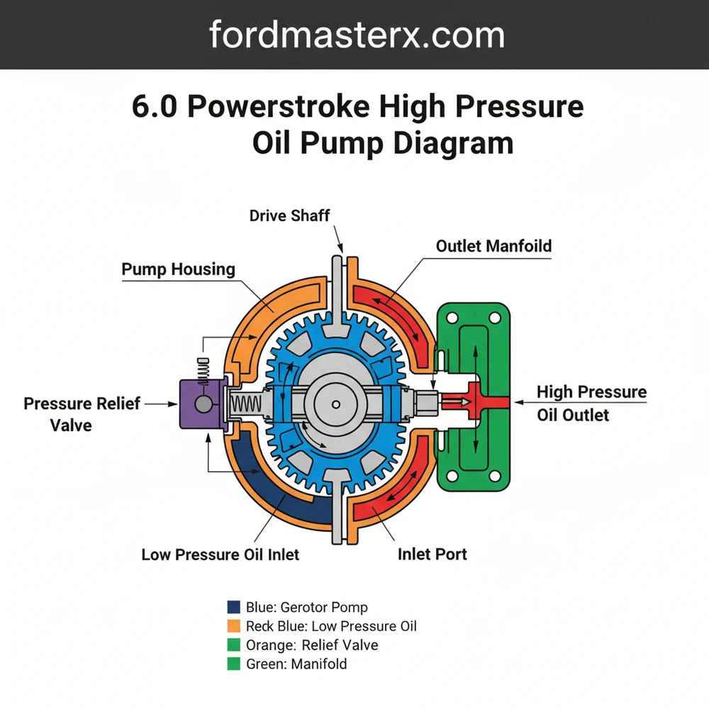
When reviewing a 6.0 powerstroke high pressure oil pump diagram, it is essential to recognize that the HPOP is located at the rear of the engine block, tucked beneath the turbocharger and the HPOP cover. The schematic typically highlights the oil flow path starting from the oil reservoir located under the oil cooler. From this reservoir, the pump draws filtered oil and compresses it to pressures ranging from 500 PSI at idle to nearly 4,000 PSI under heavy load.
The layout of the system is a masterpiece of compact engineering. In a standard blueprint of this system, you will find the Injection Pressure Regulator (IPR) valve threaded into the back of the HPOP or the pump cover. This valve is the primary control component, acting as the “brain” that modulates pressure by dumping excess oil back into the crankcase. The schematic also identifies the discharge path—in later models, this involves a “Snap-To-Connect” (STC) fitting and a branch tube that splits the oil flow to the two cylinder head oil rails. In earlier configurations, a “J-tube” serves a similar purpose. Recognizing these variations in the structure is vital because the failure points differ significantly between the two configurations. An overview of the layout also shows the HPO (High Pressure Oil) rails, which distribute the pressurized oil to each of the eight fuel injectors. The diagram serves as a blueprint for tracing leaks, which are the most common cause of “no-start” conditions in these engines.
[DIAGRAM_PLACEHOLDER: A detailed 6.0 Powerstroke High Pressure Oil Pump schematic showing the pump assembly, IPR valve, STC fitting, branch tubes, and the connection to the standpipes and dummy plugs.]
Step-by-Step Guide: How to Read and Interpret the HPOP Diagram
Interpreting a 6.0 powerstroke high pressure oil pump diagram requires a systematic approach. It is not merely a picture of parts but a map of hydraulic flow. To effectively use a schematic for your repair or inspection, follow these steps to translate the drawing into real-world action.
- ✓ Step 1: Identify Your Build Date – Look at the driver’s side valve cover for the engine manufacture date. This determines if your diagram should show the aluminum “early” pump or the cast-iron “late” pump. The routing of the discharge tubes varies significantly between these two.
- ✓ Step 2: Trace the Supply Path – Locate the oil reservoir in the diagram. This is where the low-pressure oil pump sends oil to be utilized by the HPOP. If the diagram shows a lack of oil here, the issue lies in the low-pressure side, not the HPOP itself.
- ✓ Step 3: Locate the IPR Valve – Find the IPR valve on the schematic. Note how it is positioned to regulate the flow out of the pump. On a physical engine, this is tucked deeply behind the intake manifold, and the diagram helps you visualize the socket angle needed for removal.
- ✓ Step 4: Map the Discharge and Fittings – Follow the lines leaving the HPOP. In later models, identify the STC fitting. This is a common failure point where the fitting separates or leaks. The diagram will show how this fitting connects the pump to the branch tube.
- ✓ Step 5: Follow the Branch Tubes to the Rails – The schematic will split into two paths. These represent the oil flow to the left and right cylinder heads. Trace these to the standpipes and dummy plugs, which are secondary high-pressure seals.
- ✓ Step 6: Visualizing the O-Ring Interfaces – Use the blueprint to identify every junction point. Every line on the diagram represents a potential leak site. Specifically, look for the D-rings on the standpipes and the O-rings on the injectors.
When using a diagram to perform an air leak test, focus on the IPR port. By applying shop air through the IPR port as shown in the configuration, you can listen for “gurgling” or “hissing” at the specific component locations identified on the schematic.
To perform these tasks safely, you will need a specific set of tools including a 1/2-inch drive torque wrench, a turbo-mount socket, and an IPR valve socket. Always wear eye protection, as the high-pressure oil system can retain significant pressure even after the engine is turned off. Never attempt to loosen a high-pressure fitting while the engine is cranking.
Common Issues & Troubleshooting with the HPOP System
The 6.0 Powerstroke is notorious for high-pressure oil leaks, and the 6.0 powerstroke high pressure oil pump diagram is your best defense against these problems. The most frequent issue is a “No Start Hot” condition. This occurs because engine oil thins out as it heats up, allowing it to bypass worn-out seals in the HPO system. If the pressure doesn’t reach at least 500 PSI, the PCM will not command the injectors to fire.
Common failure points include the STC fitting on later models, which can crack or completely blow off. On earlier models, the swash-plate pump itself often suffers internal mechanical failure. The IPR valve screen is another frequent culprit; if the screen is torn or clogged with debris, as seen in many system overviews, the valve may stick open, preventing pressure build-up. By using the diagram to identify these specific components, you can perform targeted tests, such as monitoring ICP (Injection Control Pressure) voltage, to narrow down whether the pump is failing or if a simple O-ring has blown out.
Debris is the number one enemy of the HPOP. Even a tiny speck of dirt introduced during a repair can ruin the IPR valve or damage the internal ceramic components of the pump. Maintain surgical cleanliness when the HPOP cover is removed.
Maintenance Tips & Best Practices
Maintaining the integrity of the high-pressure oil system is far more cost-effective than a full HPOP replacement. First and foremost, use only high-quality, OEM-spec filters and 5W-40 full synthetic oil. Because the HPOP shears oil at such high pressures, the oil breaks down faster than in a traditional diesel engine. Changing your oil every 5,000 miles is the best way to protect the pump’s internal structure.
If you have a later model engine, one of the best preventative measures is to replace the original two-piece STC fitting with the updated one-piece support bracket kit. This eliminates the most common leak source in the entire configuration. Additionally, whenever you have the valve covers off for other work, consider replacing the standpipes and dummy plugs with the updated versions that feature backup washers. These updated components are designed to withstand the heat cycles that cause original seals to fail. When purchasing a replacement pump, avoid “cheap” aftermarket units. The HPOP is a high-precision component; opting for a remanufactured unit from a reputable diesel specialist or a new OEM pump will save you from having to do the same 10-hour labor job twice. Finally, always check the IPR valve screen whenever the system is opened; it is a “window” into the health of your engine’s oil system.
In conclusion, the 6.0 powerstroke high pressure oil pump diagram is an indispensable tool for any owner or technician. By understanding the system’s schematic, from the oil reservoir to the fuel injectors, you can diagnose issues with precision and perform repairs that last. Whether you are dealing with a frustrating no-start or simply performing preventative maintenance, a clear grasp of the HPOP layout ensures your Powerstroke remains a powerhouse on the road.
Frequently Asked Questions
Where is the 6.0 Powerstroke HPOP located?
The high pressure oil pump is located at the rear of the engine valley, beneath the turbocharger and IPR valve. To access this component, you must remove the intake manifold and the HPOP cover. Its specific structure is tucked deep within the engine’s configuration to stay protected from external debris.
What does the HPOP diagram show?
This diagram displays the flow of oil from the low-pressure pump into the HPOP reservoir and then through the pump to the oil rails. It illustrates the layout of the branch tubes and standpipes, helping users visualize how oil pressure reaches each fuel injector for engine combustion.
How many connections does the HPOP system have?
The system features several critical connections, including the HPOP inlet, the IPR valve mounting port, and the high-pressure outlet fitting. There are also multiple O-rings and seals within the branch tube structure that maintain the high pressures necessary for the fuel injection system to function correctly under load.
What are the symptoms of a bad HPOP?
Common symptoms of a failing HPOP include hard starting when the engine is hot, sudden stalling, and a complete no-start condition. Low ICP (Injection Control Pressure) readings on a scan tool often indicate a leak in the system configuration or a physical failure of the pump component itself.
Can I replace the 6.0 HPOP myself?
Replacing the HPOP is a complex DIY task that requires advanced mechanical skills and several hours of labor. You must remove the turbocharger and intake manifold to reach the pump. While possible for experienced hobbyists, many prefer professional installation due to the intricate nature of the high-pressure oil system.
What tools do I need for HPOP replacement?
You will need a standard socket set, torque wrench, and a specialized IPR valve socket. Additionally, an air leak test kit is vital for verifying the system’s integrity after reassembly. Having a shop vacuum to clean the engine valley before opening the HPOP cover is also highly recommended.


