6.0 Powerstroke Glow Plug Diagram: System Setup Guide
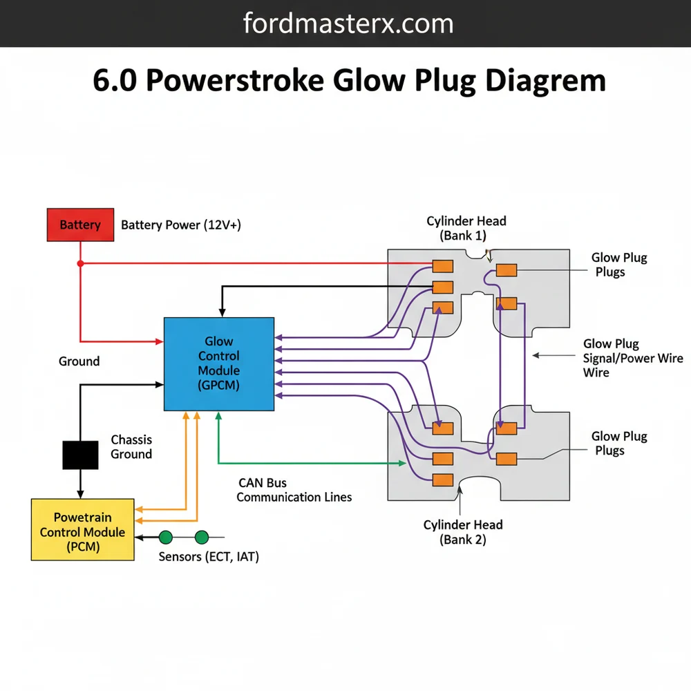
The 6.0 Powerstroke glow plug diagram illustrates the electrical path from the Glow Plug Control Module (GPCM) to the individual heaters. It details the wiring harness layout and connector configuration for each cylinder bank, ensuring the system provides the necessary heat to the combustion chamber for efficient cold engine starting.
📌 Key Takeaways
- Provides a visual map of the wiring between the GPCM and individual plugs
- The Glow Plug Control Module (GPCM) is the central component to identify
- Always disconnect batteries to prevent electrical shorts during system testing
- Use a dedicated removal tool to avoid damaging the fragile harness structure
- Consult this diagram when diagnosing P0671-P0678 fault codes
For diesel truck owners, few things are as frustrating as a hard start on a cold morning. If you own a 6.0L Powerstroke engine, the glow plug system is the heartbeat of your cold-weather starting reliability. Understanding the 6.0 powerstroke glow plug diagram is not just about looking at lines on a page; it is about grasping the synergy between the Glow Plug Control Module (GPCM), the complex wiring harnesses, and the eight individual heating elements that warm the combustion chambers. This comprehensive guide will walk you through the entire system structure, providing the blueprint you need to diagnose, repair, and maintain your truck’s starting system with professional accuracy.
Unlike older 7.3L engines that used a simple relay, the 6.0L Powerstroke utilizes a sophisticated GPCM. This module can detect a failure in a single glow plug and report a specific diagnostic trouble code (DTC) for that exact cylinder, making the wiring schematic much more detailed than earlier models.
Decoding the 6.0 Powerstroke Glow Plug Diagram and System Layout
The 6.0 powerstroke glow plug diagram reveals a highly organized but cramped system. To read it effectively, you must first identify the primary components that constitute the system architecture. The system is split into two “banks”—the passenger side (right bank) and the driver side (left bank). The central brain of this operation is the GPCM, which is typically mounted on a bracket near the driver-side valve cover.
The schematic shows two main electrical connectors plugging into the GPCM. These are often color-coded: one is black and the other is green. Each connector services a specific side of the engine. The wiring layout then branches out into a specialized harness that snakes under the heat shields and plugs into the four glow plugs on each bank. In the 6.0L configuration, the glow plugs are positioned deep within the cylinder head, accessed through the valve covers via specialized rubber boots on the harness.
[DIAGRAM_PLACEHOLDER: A detailed schematic showing the GPCM at the center, with Green and Black connectors. Lines branch out to four cylinders on the Left (2, 4, 6, 8) and four on the Right (1, 3, 5, 7). Include labels for the power feed from the battery and the communication link to the PCM.]
One critical variation to look for in your blueprint is the model year transition. Early versions of the 6.0L (manufactured before 2004.5) featured a different harness style compared to the later versions. The late-model layout utilizes a “bus bar” style harness integrated into a rigid plastic rail, which can be more difficult to remove without the proper tools. The diagram also illustrates the heavy-gauge power supply wires that come directly from the battery junction, protected by high-amp fusible links. Understanding this power flow is essential because a break in the main power line will disable all eight plugs simultaneously.
Step-by-Step Guide to Interpreting and Using the Diagram

Navigating a 6.0 powerstroke glow plug diagram requires a methodical approach. Whether you are performing a routine check or a full replacement, follow these steps to ensure you are interpreting the system correctly.
- ✓ Step 1: Identify the Bank and Cylinder: Locate the specific cylinder throwing a fault code. In the Powerstroke layout, cylinders 1, 3, 5, and 7 are on the passenger side, while 2, 4, 6, and 8 are on the driver side.
- ✓ Step 2: Trace the Connector: Use the diagram to identify which GPCM connector services that cylinder. Typically, the green connector handles the passenger side and the black handles the driver side.
- ✓ Step 3: Test Continuity: Using a multimeter, check the resistance between the GPCM pin (as identified on the schematic) and the end of the harness. A reading of 0.5 to 2.0 ohms is generally considered healthy for the plug itself.
- ✓ Step 4: Verify Power Supply: Locate the two large red wires on the diagram. These provide the high-amperage 12V current to the module. Ensure these wires show battery voltage when the key is in the “On” position.
- ✓ Step 5: Inspect Communication Lines: The diagram will show smaller wires connecting the GPCM to the Powertrain Control Module (PCM). This is how the engine knows when to activate the plugs based on oil temperature.
- ✓ Step 6: Access the Plugs: To physically reach the components shown in the blueprint, you will need to remove the inner fender liners. This provides a direct line of sight to the glow plug harness boots.
Never test the GPCM by “jumping” the terminals with a screwdriver. The module contains sensitive solid-state electronics that can be instantly fried by a high-amperage surge. Always use a high-quality digital multimeter for diagnostic work.
Necessary Tools and Materials
Before attempting to follow the 6.0 powerstroke glow plug diagram for a repair, gather these essentials:
1. Digital Multimeter (DMM)
2. 10mm Deep Well Socket (for glow plug removal)
3. Glow Plug Harness Removal Tool (specifically for 6.0L)
4. Torque Wrench (capable of low inch-pound settings)
5. Dielectric Grease (for harness connections)
Common Issues and Troubleshooting with the Glow Plug System

When your truck fails to start or emits white smoke upon ignition, the 6.0 powerstroke glow plug diagram becomes your primary diagnostic tool. The most frequent failure point is the wiring harness itself. Due to the high heat environment of the 6.0L engine, the plastic connectors often become brittle and crack. If the diagram shows a complete circuit but your multimeter shows an “open” reading, the harness is likely broken internally.
Another common issue is “glow plug tip swelling.” This happens when a plug fails internally and the heating element expands. If you consult your layout and find that the resistance is infinitely high, you must be extremely careful during removal. A swollen tip can break off inside the cylinder head, leading to catastrophic engine damage.
If you are getting codes for multiple cylinders on the same bank (e.g., P0671, P0673, P0675, P0677), the problem is rarely the plugs themselves. It is almost certainly the harness or the GPCM. Check the diagram for the common power feed shared by that bank before replacing individual parts.
Diagnostic codes P0671 through P0678 correspond directly to cylinders 1 through 8. If you see P0670, this indicates a general failure in the control circuit, meaning the GPCM itself is likely the culprit or has lost its primary ground connection. Always verify the ground wires shown on the schematic before condemning an expensive control module.
Maintenance Tips and Best Practices
To keep your 6.0L Powerstroke starting reliably, maintenance is key. One of the best practices is to replace your glow plug harnesses whenever you are performing other top-end engine work, such as injector replacement or standpipe updates. Since the harnesses must be removed anyway, installing new ones ensures that the brittle plastic connectors don’t fail shortly after reassembly.
Regarding component quality, there is a consensus among Powerstroke experts: only use OEM Motorcraft glow plugs. Aftermarket plugs often have different heating rates or physical dimensions that can trigger false codes in the GPCM or, worse, swell and break off in the head. The ZB-11 glow plug is the standard for the 6.0L and is designed to work perfectly with the factory GPCM voltage curves.
- ✓ Use Dielectric Grease: Apply a small amount to the harness boots to prevent moisture intrusion and make future removals easier.
- ✓ Observe Torque Specs: Glow plugs should be torqued to approximately 124 inch-pounds. Over-tightening can crack the ceramic insulator.
- ✓ Check Batteries First: The GPCM is very sensitive to voltage drops. If your batteries are weak, the glow plugs may not stay energized long enough to start the engine, even if the diagram shows the system is wired correctly.
In summary, a 6.0 powerstroke glow plug diagram is a vital resource for any owner looking to maintain their diesel engine’s performance. By understanding the relationship between the GPCM, the dual-bank harness system, and the individual plugs, you can move from guesswork to precision diagnostics. Whether you are chasing a specific P067X code or performing a complete system overhaul, keeping this schematic and these best practices in mind will ensure your Powerstroke remains ready to work, no matter how low the temperature drops. Proper identification of components and a methodical testing approach are the hallmarks of a successful repair.
Frequently Asked Questions
Where are the glow plugs located?
On the 6.0 Powerstroke, glow plugs are located underneath the valve covers on both the driver and passenger sides. They are installed deep into the cylinder head structure. Accessing them typically requires removing the inner fender liners or various intake components to reach the specialized wiring harness.
What does the 6.0 Powerstroke glow plug diagram show?
The diagram shows the complete electrical configuration of the heating system. It identifies the two main GPCM connectors, the wire color-coding for each cylinder, and the routing layout. This help users pinpoint which wire corresponds to a specific cylinder when troubleshooting a localized circuit failure.
How many connections does the GPCM have?
The Glow Plug Control Module features a dual-connector system, typically consisting of a green and a black plug. These connectors interface with the engine’s power supply and the individual glow plug harnesses. Each pin in the layout is assigned to a specific cylinder or power ground terminal.
What are the symptoms of a bad glow plug?
Symptoms include hard starting in cold weather, excessive white smoke during startup, and a rough idle that smooths out as the engine reaches operating temperature. A failed component often triggers a Check Engine Light with codes P0671 through P0678, indicating which specific cylinder circuit is malfunctioning.
Can I replace 6.0 Powerstroke glow plugs myself?
Yes, but the task requires patience due to the cramped engine bay layout. You must be careful not to break the brittle plastic harness clips. Utilizing a proper diagram and the correct removal tools makes the process manageable for a DIYer with moderate mechanical experience.
What tools do I need for this task?
Essential tools include a 10mm deep-well socket, a glow plug harness removal tool, and a multimeter for testing resistance. Because the system layout is sensitive, using a torque wrench during installation is vital to ensure the plugs are seated correctly without over-tightening or damaging the threads.


