6.0 Powerstroke Cooling System Diagram: Complete Guide
A 6.0 Powerstroke cooling system diagram illustrates the complex flow of coolant through the water pump, engine block, cylinder heads, and critical components like the oil cooler and EGR cooler. It serves as a visual map for diesel owners to identify leak points and ensure proper heat management for engine longevity.
📌 Key Takeaways
- Identifies the flow path between the radiator, oil cooler, and EGR cooler
- The oil cooler is the most critical component to monitor for clogging
- Always use a pressure tester to safely identify leaks without injury
- Referencing the diagram helps diagnose overheating issues before failure occurs
- Use this diagram during routine coolant flushes or water pump replacement
The 6.0L Powerstroke diesel engine is renowned for its impressive torque and towing capabilities, but it is equally famous among enthusiasts and mechanics for its sensitive thermal management requirements. Understanding a comprehensive 6.0 powerstroke cooling system diagram is not just a luxury for the backyard mechanic; it is a critical necessity for ensuring the long-term survival of the engine. This guide provides a detailed breakdown of how coolant moves through the block, heads, and various heat exchangers that define this complex system. By the end of this article, you will be able to identify every major component, understand the sequence of the coolant flow, and use this knowledge to diagnose common failure points before they lead to expensive repairs. Whether you are replacing a water pump or troubleshooting a high-temperature delta, having a clear visual and conceptual map of the system is your first line of defense against catastrophic engine failure.
Detailed Breakdown of the Cooling System Diagram
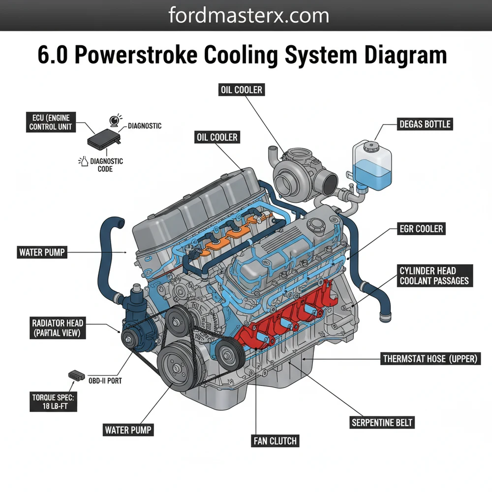
The 6.0 powerstroke cooling system diagram is characterized by its “split-flow” design, which manages heat for both the engine oil and the Exhaust Gas Recirculation (EGR) system. Unlike simpler gasoline engines, the 6.0 Powerstroke utilizes a heavy-duty water pump driven by the accessory belt rather than a timing chain. This pump is the heart of the system, circulating a mixture of water and antifreeze through a specific path to maintain an optimal operating temperature.
In the diagram, you will observe the coolant starting its journey at the radiator, where it is cooled by airflow. From the bottom of the radiator, it is pulled into the water pump. The pump then pushes the coolant into the front cover and through the engine block. A significant portion of this flow is directed into the “valley” of the engine, where the oil cooler is located. The diagram visually represents this as a critical intersection: the coolant must pass through the tiny passages of the oil cooler to absorb heat from the engine oil. After exiting the oil cooler, a portion of the coolant is diverted to the EGR cooler, while the rest returns to the engine block and cylinder heads.
Most diagrams use color-coding to signify temperature: Bright blue represents the “cold” side (post-radiator), while dark red represents the “hot” side (post-engine). In the 6.0 Powerstroke, pay close attention to the purple or orange lines often used to denote the bypass circuit and the degas bottle return lines.
[DIAGRAM_PLACEHOLDER – A technical schematic showing the radiator, water pump, oil cooler, EGR cooler, thermostat housing, and degas bottle with flow arrows indicating the path from the pump through the block and back through the radiator.]
Finally, the coolant reaches the thermostat housing. If the engine is at operating temperature, the thermostat opens, allowing the hot fluid to return to the radiator. If the engine is cold, the coolant recirculates through a bypass. The degas bottle, positioned at the highest point of the system, acts as a pressurized reservoir that removes air bubbles from the coolant flow, ensuring that the system remains primed and free of air pockets that could cause localized overheating.
Step-by-Step Guide: Reading and Applying the Diagram

Interpreting a technical diagram can be daunting, but following a logical sequence makes the process straightforward. Use the following steps to trace the system on your vehicle and understand how the components interact during operation.
- 1. Locate the Degas Bottle: Start at the coolant reservoir (degas bottle) on the driver’s side. This is your reference point for system pressure and fluid level. Ensure the cap is rated for 16 PSI to maintain the boiling point of the coolant.
- 2. Trace the Low-Pressure Supply: Follow the large hose from the bottom of the degas bottle or radiator to the water pump. Note the condition of the accessory belt; if the belt slips, the water pump loses efficiency, leading to rapid temperature spikes.
- 3. Identify the Oil Cooler Housing: Look into the valley of the engine (under the intake manifold). The diagram shows the coolant entering this housing first. This is a primary failure point where silicate dropout can clog the small cooling fins.
- 4. Follow the EGR Cooler Path: From the oil cooler, trace the short “J-tube” or hose that leads to the EGR cooler. The diagram illustrates how the EGR cooler relies on the oil cooler for its supply of coolant. If the oil cooler clogs, the EGR cooler is starved, which often leads to internal ruptures.
- 5. Locate the Thermostat and Housing: Move to the top front of the engine. The thermostat regulates when coolant is allowed to return to the radiator. When reassembling this area, always refer to the torque spec of 15-20 lb-ft for the housing bolts to prevent housing distortion.
- 6. Connect to the ECU Monitoring: Understand that the ECU (Engine Control Unit) monitors the Engine Coolant Temperature (ECT) and Engine Oil Temperature (EOT) sensors. If the diagram shows a disparity in flow, the ECU will detect a “delta” and may trigger a check engine light.
Never open the degas bottle cap when the engine is hot. The 6.0 Powerstroke operates under high pressure, and escaping steam can cause severe burns. Always wait for the EOT to drop below 120°F before servicing the system.
To properly diagnose the system, you will need a few essential tools. An OBD-II scan tool is vital for reading live data from the sensors. You will also need a cooling system pressure tester, a vacuum refill tool (to prevent airlocks), and basic hand tools including 10mm and 12mm sockets. When inspecting the accessory belt, check the tensioner to ensure it is providing enough force to turn the large water pump pulley without slipping under load.
Common Issues and Troubleshooting
The 6.0 Powerstroke cooling system is often the subject of “bulletproofing” discussions because of a few specific vulnerabilities. The most frequent issue is the clogging of the oil cooler. Because the oil cooler acts as a filter for the coolant before it reaches the EGR cooler, any debris or silicate dropout will lodge itself in the oil cooler’s narrow passages. This results in a high temperature “delta”—a difference between oil and coolant temperatures that exceeds 15 degrees Fahrenheit during highway cruising.
When these temperatures diverge, the ECU often generates a diagnostic code such as P0128 (Thermostat Malfunction) or codes related to EGR performance. If you see a check engine light, use an OBD-II monitor to check the ECT and EOT. If the oil temperature is significantly higher than the coolant temperature, the diagram tells you the blockage is in the valley of the engine. Another common sign of trouble is “puking” coolant from the degas bottle. This usually indicates that high-pressure combustion gases are leaking into the cooling system through a failed head gasket or a ruptured EGR cooler, overcoming the 16 PSI cap.
If you suspect a head gasket leak versus an EGR cooler leak, park the truck on an incline with the nose down. If coolant accumulates in the intake manifold, the EGR cooler is the likely culprit. If the pressure builds immediately upon a cold start, suspect the head gaskets.
Tips and Best Practices for Maintenance
Maintaining the integrity of the 6.0 powerstroke cooling system diagram requires proactive care rather than reactive repairs. One of the best investments you can make is the installation of a coolant filtration system. These bypass filters tap into the coolant flow and remove the casting sand and chemical deposits that lead to oil cooler failure. By removing these particulates, you extend the life of the water pump seals and the internal heat exchangers.
Furthermore, the type of coolant used is critical. Many experts recommend switching from the original gold coolant to a heavy-duty Extended Life Coolant (ELC) that meets the EC-1 specification. Gold coolant contains silicates that can “drop out” of solution when exposed to the high localized heat of the EGR cooler, creating a sandpaper-like sludge. ELC coolants are silicate-free and significantly reduce the risk of clogging the oil cooler. Always perform a thorough flush with distilled water before switching types to avoid chemical reactions.
- ✓ Monitor the Deltas: Use an electronic monitor to keep an eye on EOT and ECT at all times.
- ✓ Check the Accessory Belt: Ensure the belt is free of cracks and the tensioner is firm to keep the water pump spinning at full RPM.
- ✓ Observe Torque Specs: When replacing the thermostat or water pump, use a calibrated torque wrench to ensure even sealing.
- ✓ Replace the Cap: The degas bottle cap is a wear item. Replace it every two years to ensure the system holds the proper 16 PSI of pressure.
By following these best practices and using the 6.0 powerstroke cooling system diagram as your roadmap, you can transform a notoriously sensitive engine into a reliable workhorse. Regular maintenance and a deep understanding of the coolant’s path through the engine will save you thousands of dollars in repairs and keep your truck on the road for hundreds of thousands of miles.
Frequently Asked Questions
Where is the thermostat located?
The thermostat is located inside a dedicated housing on the upper front of the engine block. It is connected directly to the upper radiator hose. Following the cooling system diagram will show its position relative to the water pump and the bypass circuit used during engine warm-up phases.
What does this cooling system diagram show?
The diagram shows the complete circulation path of the coolant, including the radiator, degas bottle, oil cooler, and heater core. It maps how coolant travels through the engine block to absorb heat and how it is channeled through the EGR cooler to lower exhaust gas temperatures before recirculation.
How many connections are in the cooling system?
The system features several primary connections including the upper and lower radiator hoses, heater core supply lines, and the degas bottle return. Additionally, there are critical internal connections between the oil cooler and EGR cooler that must remain sealed to prevent coolant from entering the combustion chamber.
What are the symptoms of a bad oil cooler?
Common symptoms include a high temperature delta between oil and coolant, often triggering a check engine light. If the cooler is failing, you may see a diagnostic code related to engine over-temperature. In severe cases, oil may leak into the coolant, creating a thick sludge in the degas bottle.
Can I replace the water pump myself?
Yes, a DIY enthusiast can replace the water pump by following the diagram. It requires removing the fan shroud and ensuring you use the correct torque spec for the mounting bolts. Proper installation is vital to prevent leaks and ensure the belt drive system operates without any slippage.
What tools do I need for cooling system maintenance?
You will need a basic socket set, a torque wrench, and a drain pan. For advanced troubleshooting, an OBD-II scanner is essential to monitor real-time temperature data from the ECU. This allows you to verify that the cooling system is operating within the manufacturer’s specified temperature ranges.


