6.0 Powerstroke Air Intake Diagram: Full System Guide
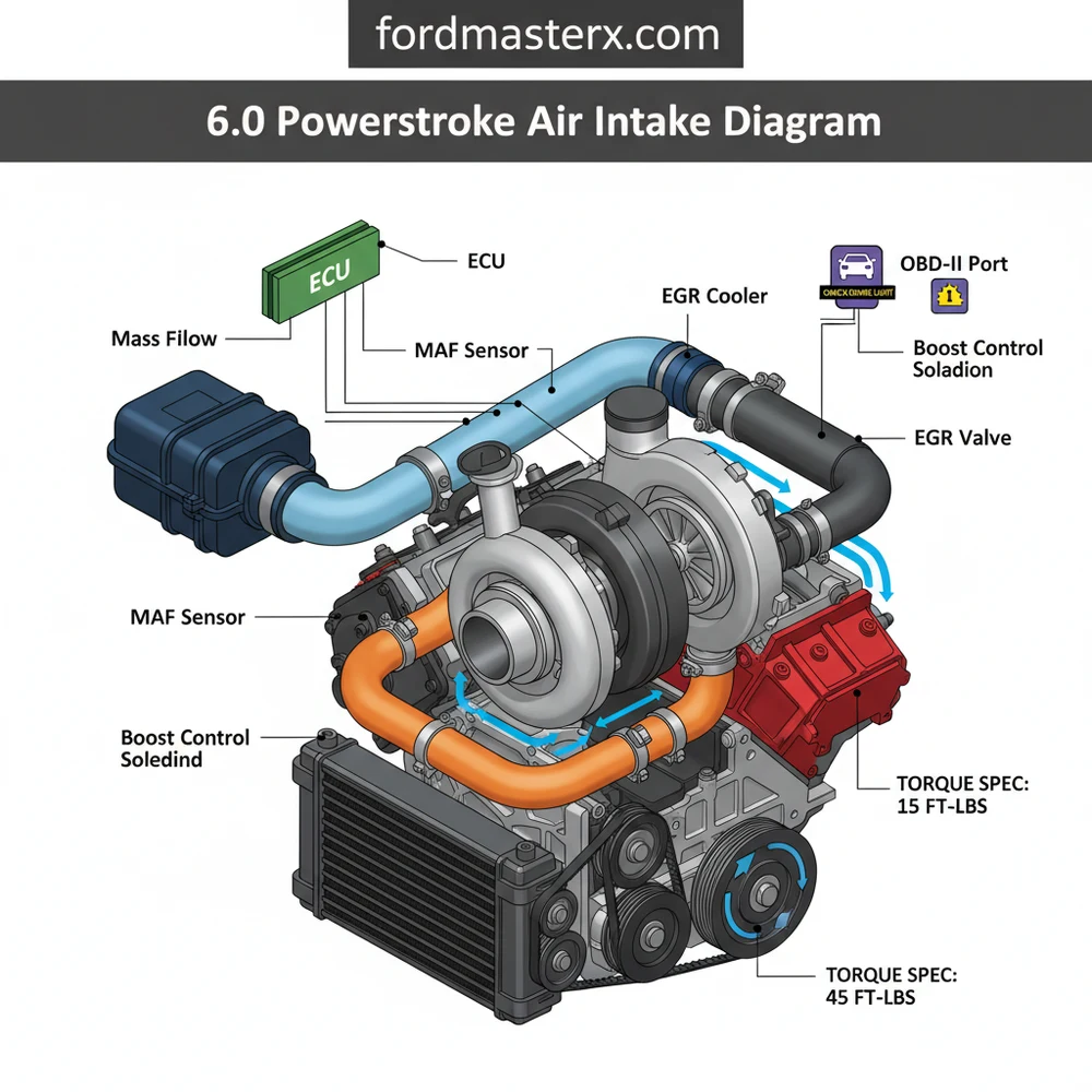
A 6.0 Powerstroke air intake diagram illustrates the airflow path starting from the filter housing, through the mass airflow sensor, and into the turbocharger inlet. Understanding this layout is essential for locating vacuum leaks or sensor failures that trigger a check engine light or specific diagnostic code during operation.
📌 Key Takeaways
- The diagram visualizes the flow from the air box to the turbocharger compressor
- The Mass Airflow (MAF) sensor is the most critical electronic component to identify
- Ensure all silicone boots are free of oil to prevent them from slipping under pressure
- Always tighten intercooler pipe clamps to the manufacturer torque spec to avoid boost leaks
- Use this diagram when diagnosing low boost, excessive smoke, or high EGTs
The Ford 6.0L Powerstroke diesel engine, produced between 2003 and 2007, is a powerhouse known for its specific maintenance requirements and unique engineering. One of the most critical systems for maintaining the longevity of this engine is the air intake system. Unlike many gasoline engines, the 6.0 Powerstroke utilizes a highly efficient, high-capacity dry-filter system designed by Donaldson. For DIY enthusiasts, understanding the 6.0 Powerstroke air intake diagram is the first step in diagnosing performance issues, performing routine maintenance, or installing aftermarket upgrades. This article provides a comprehensive breakdown of the intake anatomy, flow path, and technical specifications needed to keep your Super Duty breathing clean air.
Main Components and Features
The stock air intake system on a 6.0 Powerstroke is often cited as one of the best factory designs in the diesel world, capable of supporting up to 500 horsepower. However, it is complex. Understanding the diagram requires identifying several key components located primarily on the driver-side front of the engine compartment.
- The Air Inlet (Snorkel): This is the starting point of the system. It is a plastic duct located behind the driver-side headlight. It is designed to pull “cool” ambient air from outside the engine bay rather than the hot air radiating off the radiator and engine block.
- The Lower Filter Housing (The Bucket): The snorkel feeds directly into the lower housing. This large plastic tub holds the massive cylindrical air filter. It is secured to the chassis with rubber grommets to dampen engine vibration.
- The Donaldson Air Filter: The heart of the system is the “Powerstroke Blue” filter. It is a nanofiber dry media filter. It features a large surface area and is designed to trap 99.9% of contaminants. Dimensions are approximately 10 inches in diameter and 12 inches in length.
- The Upper Housing (Lid) and MAF Sensor: The lid of the airbox secures the filter in place. Integrated into this lid is the Mass Air Flow (MAF) sensor and the Intake Air Temperature (IAT) sensor. The MAF sensor is held in by two T-20 Torx security screws.
- The Filter Minder: Located on the side of the airbox or the intake tube, this is a mechanical vacuum gauge. It measures the restriction level. As the filter gets dirty, the yellow indicator moves into the red zone, signaling that a replacement is necessary.
- Intake Bellows and Tubing: A large 4-inch diameter plastic tube connects the airbox to the turbocharger inlet. It includes a flexible accordion-style “bellows” section that allows the engine to move on its mounts without cracking the rigid plastic intake components.
How to Read and Use the Intake Diagram

When looking at a 6.0 Powerstroke air intake diagram, you are looking at a flow chart of air and a map of electronic signals. To use the diagram effectively for DIY repairs, follow the air’s journey from the atmosphere to the turbocharger compressor wheel.
1. The Air Flow Path: In a standard diagram, you will see air entering at the front-left (driver side). It moves through the snorkel, into the outer chamber of the filter housing, passes through the blue media into the hollow center of the filter, and exits through the MAF sensor housing. From there, it travels through the 4-inch intake ducting directly into the “cold side” of the Garrett GT3782VA turbocharger.
2. Electrical Connections and Wire Colors: For those troubleshooting “Check Engine” lights (CEL), the wiring at the MAF/IAT sensor is vital. The sensor typically uses a 6-pin connector. While colors can vary slightly by year (2003 vs 2006), the standard 6.0L MAF wiring diagram generally follows this pattern:
- Pin 1 (Red/Black): 12V Power Source.
- Pin 2 (Black/White): Ground.
- Pin 3 (Tan/Light Blue): MAF Signal.
- Pin 4 (Light Blue/Red): MAF Signal Return.
- Pin 5 (Grey): IAT Sensor Signal.
- Pin 6 (Grey/Red): IAT Signal Return.
3. Measuring Clearances: When inspecting the intake according to the diagram, check the clearance between the intake tube and the degas bottle (coolant reservoir). Over time, vibration can cause the intake tube to rub against the degas bottle or the FICM (Fuel Injection Control Module) mounting brackets, leading to holes in the plastic that allow unfiltered air into the engine.
Maintenance and DIY Tips

Maintaining the 6.0 Powerstroke intake is straightforward but requires attention to detail. Because this engine uses a Variable Geometry Turbo (VGT), even small amounts of dust can cause the internal vanes to stick or the compressor wheel to “dust” (wear down prematurely).
- Filter Replacement Interval: Do not change the filter based on mileage alone. The Donaldson filters are expensive (often $80-$120) and are designed to hold a significant amount of dirt. Use the Filter Minder. If the indicator hasn’t moved into the “change” zone, leave the filter alone. Opening the airbox unnecessarily increases the risk of improper sealing.
- Cleaning the MAF Sensor: If you experience a slight drop in fuel economy or a “hiccup” under acceleration, the MAF sensor might be dirty. Use a dedicated MAF sensor cleaner spray. Never touch the delicate wires inside the sensor with your fingers or a cotton swab, as oil and fibers will ruin the sensor.
- Sealing the Housing: When reinstalling the filter, ensure the rubber gasket at the end of the filter is seated perfectly against the rear of the housing. If this seal is not airtight, the turbo will suck in “unmetered” and unfiltered air, bypassing the filter entirely.
Troubleshooting Common Intake Issues
If you are using an intake diagram to solve a specific problem, you are likely dealing with one of the following common 6.0 Powerstroke ailments:
1. P0101, P0102, or P0103 Codes
These codes relate to the MAF sensor. If your diagram shows all connections are secure, check for a “boost leak” or an intake obstruction. A common DIY fail is leaving a rag in the intake during maintenance. More likely, a cracked intake bellows is allowing air to enter behind the sensor, causing the computer to see a mismatch between the MAF reading and the actual air entering the turbo.
2. Turbo Surge or “Chuffing”
If you hear a “whoosh-whoosh” sound when letting off the throttle, it is often called turbo surge. While this is sometimes related to the VGT vanes, it can also be caused by a severely restricted air filter. Check the Filter Minder. If it is sucked all the way into the red, your engine is struggling to breathe, creating a vacuum that can destabilize the turbocharger compressor wheel.
3. “Dusting” the Turbo
Dusting occurs when dirt bypasses the filter and acts like sandpaper on the turbo’s compressor wheel. To troubleshoot this, remove the intake tube from the turbo inlet (usually a 5/16″ or 8mm nut on the constant-tension clamp). Inspect the wheel. If the edges of the blades are rounded, pitted, or “sharp,” you have a leak in your intake system. Refer to your diagram to check every junction, specifically the seal between the filter and the housing lid.
4. Loose Clamps and Boots
The 6.0 Powerstroke generates significant vibration. Over time, the clamps holding the intake tube to the turbo can vibrate loose. Ensure the clamp is positioned behind the “bead” on the turbo inlet to prevent it from slipping off under load. The torque spec for these small clamps is generally very low (around 35-45 inch-pounds); do not over-tighten, or you will crack the plastic intake tube.
Conclusion
The 6.0 Powerstroke air intake system is a masterclass in filtration, but it requires a disciplined approach to maintenance. By understanding the flow diagram—from the cold air snorkel to the MAF sensor and down into the turbo—DIYers can prevent the most common causes of engine wear. Always prioritize the integrity of the seals and the cleanliness of the MAF sensor. Whether you are keeping the legendary stock Donaldson setup or moving to a high-flow aftermarket system, the principles of the air intake diagram remain the same: provide the coolest, cleanest, and most unrestricted air possible to the turbocharger. Proper care here doesn’t just improve performance; it protects the very heart of your diesel engine.
Step-by-Step Guide to Understanding the 6.0 Powerstroke Air Intake Diagram: Full System Guide
Identify – Start with identifying the air filter housing and the primary intake tube leading to the turbo.
Locate – Locate the MAF and IAT sensors to ensure their wiring harnesses are secure and free of debris.
Understand – Understand how the intercooler pipes (CAC tubes) transition from the turbo to the front-mounted heat exchanger.
Apply – Apply the correct torque spec to every T-bolt clamp to prevent boost leaks during high-pressure operation.
Verify – Verify that the ECU is receiving accurate airflow data by checking live parameters with an OBD-II scanner.
Complete – Complete the process by checking for any stored diagnostic code and performing a test drive to monitor boost.
Frequently Asked Questions
Where is the MAF sensor located?
The Mass Airflow (MAF) sensor is located on the plastic intake tube directly after the air filter housing. It monitors the volume of air entering the system, sending data to the ECU to manage fuel trim and ensure the engine runs efficiently without triggering a check engine light.
What does the air intake diagram show?
The diagram shows the sequential path of ambient air as it enters the filter, passes through the ducting into the turbocharger, and travels through the intercooler (CAC) pipes. It highlights connection points, sensor locations, and the structural layout of the intake manifold and turbocharger inlet.
How many boots are in the 6.0 intake system?
The system typically features four main silicone boots on the charge air cooler (CAC) pipes. Two connect the turbo to the intercooler, and two connect the intercooler to the intake manifold. Each requires heavy-duty T-bolt clamps to withstand the high boost pressures generated by the 6.0 Powerstroke engine.
What are the symptoms of a bad intake leak?
Common symptoms include a noticeable hiss under acceleration, loss of power, black smoke from the exhaust, and an illuminated check engine light. You may also see a specific diagnostic code related to underboost or MAF sensor correlation when scanning the vehicle via the OBD-II port.
Can I install an aftermarket intake myself?
Yes, installing a cold air intake on a 6.0 Powerstroke is a straightforward DIY task that requires basic hand tools. Most kits are bolt-on and do not require tuning, though monitoring your engine via OBD-II after installation is recommended to ensure the ECU is adjusting correctly to the increased airflow.
What tools do I need for intake maintenance?
You will need a standard socket set (specifically 7mm, 8mm, and 11mm for clamps), a flathead screwdriver for sensor clips, and a torque wrench. Using a torque wrench ensures you meet the exact torque spec for the boots, preventing them from blowing off under heavy engine load.


