5.4 Triton Coil Pack Diagram: Wiring & Layout Guide
A 5.4 Triton coil pack diagram illustrates the cylinder numbering and firing order for Ford’s V8 engine. It maps specific coils to their corresponding cylinders, allowing you to match a diagnostic code from an OBD-II scanner to a physical location. This is essential for replacing faulty components and restoring proper ignition timing.
📌 Key Takeaways
- Identify the correct cylinder numbering to match OBD-II codes.
- The ECU controls each coil individually for precise ignition timing.
- Always follow the manufacturer torque spec for coil mounting bolts.
- A clear diagram prevents cross-wiring during harness repairs.
- Use this diagram when diagnosing a persistent check engine light.
Understanding the 5.4 Triton coil pack diagram is essential for any Ford truck owner or mechanic attempting to diagnose a persistent engine misfire or a “hesitation” under load. The 5.4L Triton engine, a staple of the Ford modular engine family, relies on a Coil-on-Plug (COP) ignition system. Because these engines are prone to specific ignition failures, having a clear visual and technical reference allows you to identify which cylinder is failing without unnecessary guesswork. This guide provides a detailed 5.4 Triton coil pack diagram breakdown, explains how to interpret firing orders, and offers a comprehensive roadmap for troubleshooting and replacement. You will learn the exact cylinder locations, how to navigate the engine bay, and how to use diagnostic tools to pinpoint faulty components efficiently.
Decoding the 5.4 Triton Coil Pack Diagram
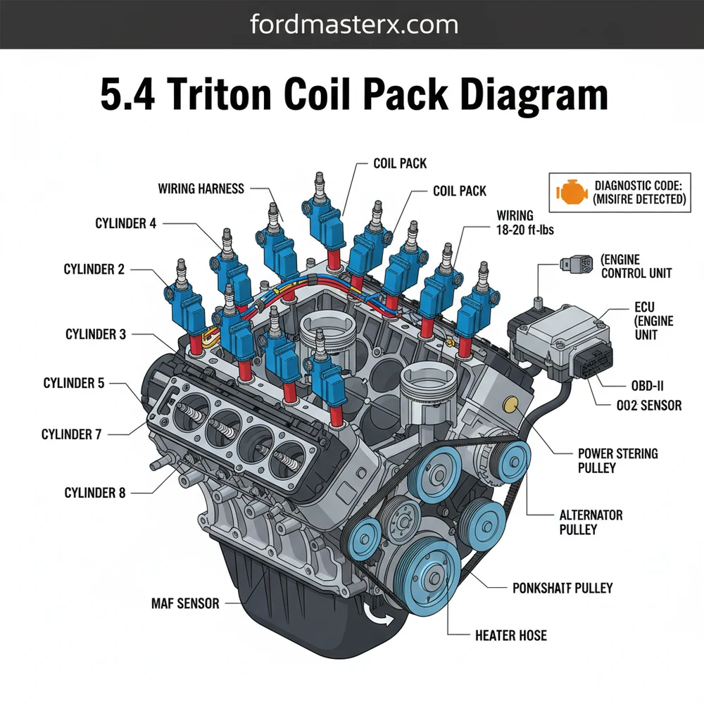
To effectively use a 5.4 Triton coil pack diagram, you must first understand the layout of the Ford V8 engine bay. Unlike some manufacturers that alternate numbers across banks, Ford uses a sequential numbering system for each bank. When you are standing at the front bumper looking toward the windshield, the cylinders are numbered as follows: The passenger side (Bank 1) contains cylinders 1, 2, 3, and 4, starting from the front of the engine near the accessory belt and moving toward the firewall. The driver’s side (Bank 2) contains cylinders 5, 6, 7, and 8, again starting from the front and moving back.
The coil packs themselves are small, individual transformers sitting directly atop each spark plug. Each coil is connected to the engine wiring harness, which receives precisely timed electrical pulses from the ECU (Engine Control Unit). The diagram below illustrates the physical location of each coil and the standard firing order, which for the 5.4L Triton is 1-3-7-2-6-5-4-8. Understanding this sequence is vital because a failure in one coil can sometimes “ghost” symptoms into another cylinder depending on how the ECU manages fuel trim and ignition timing adjustments.
BANK 1 (Passenger Side)
Front: COIL 1
COIL 2
COIL 3
Rear: COIL 4
BANK 2 (Driver Side)
Front: COIL 5
COIL 6
COIL 7
Rear: COIL 8
Note: Cylinder 4 and 8 are closest to the firewall. Cylinder 1 and 5 are closest to the radiator.
The variation between the 2-valve and 3-valve versions of the 5.4L engine primarily affects the physical shape of the coil boot and the specific torque spec required for the mounting bolt, but the overall numbering and diagrammatic layout remain consistent. The 3-valve engines, commonly found in later model trucks, feature a more integrated design where the coil is tucked deeper into the valve cover, making access to the rear cylinders (4 and 8) somewhat more challenging due to the proximity of the fuel rails and heater hoses.
On the 5.4L Triton, the ECU monitors the primary and secondary ignition circuits. If a coil fails, the system will usually trigger a check engine light and store a specific diagnostic code (P0301 through P0308) identifying which cylinder is misfiring. This correlates directly to the cylinder numbers on your diagram.
Step-by-Step Replacement and Testing Guide

Once you have identified a fault using your 5.4 triton coil pack diagram, follow these steps to safely inspect or replace the component. This process requires basic hand tools but demands patience, especially when working on the rear cylinders near the firewall.
- 1. Perform a Diagnostic Scan: Use an OBD-II scanner to read the stored fault codes. A code like P0303 indicates a misfire on cylinder 3. Locate cylinder 3 on your diagram (third one back on the passenger side) to know exactly where to work.
- 2. Clear the Area: Ensure the engine is cool. Disconnect the negative battery terminal. On many 5.4L models, you may need to move the air intake assembly or loosen the fuel rail (without disconnecting lines) to gain clear access to the coil mounting bolts.
- 3. Disconnect the Harness: Carefully depress the plastic tab on the electrical connector and pull it away from the coil. These connectors can become brittle due to engine heat, so apply gentle pressure to avoid snapping the clip.
- 4. Remove the Mounting Bolt: Using a 7mm socket (standard for most Triton COPs), remove the single bolt holding the coil pack to the intake manifold. Be careful not to drop the bolt into the engine valley or the timing chain cover area.
- 5. Extract the Coil: Pull the coil pack straight up and out of the spark plug well. You may feel some resistance as the rubber boot releases its grip on the spark plug.
- 6. Inspect the Well: Use a flashlight to look down into the spark plug well. Check for the presence of oil (indicating a leaking valve cover gasket) or coolant (indicating a leak from the intake manifold or coolant flow crossover). Moisture is the number one killer of Triton coil packs.
- 7. Install the New Coil: Apply a small amount of dielectric grease to the inside tip of the new coil boot. This prevents the rubber from sticking to the plug and helps seal out moisture. Press the coil firmly onto the plug until you feel it seat.
- 8. Torque and Reconnect: Hand-start the 7mm bolt to avoid cross-threading the plastic intake manifold. Tighten to the appropriate torque spec (usually around 40-60 inch-pounds; do not over-tighten). Reattach the electrical connector and battery terminal.
Never attempt to remove spark plugs or coils while the engine is hot. The aluminum cylinder heads on the 5.4L Triton are sensitive to temperature; removing components while hot increases the risk of stripping the threads, which can lead to the infamous “blown spark plug” issue common on earlier 2-valve models.
Troubleshooting Common Ignition Issues

When your check engine light begins flashing, it indicates a “catalyst-damaging” misfire. The 5.4 Triton coil pack diagram is your first line of defense in resolving this. Common issues often stem from more than just a worn-out coil. For instance, a failure in the timing chain tensioners can cause erratic timing that the ECU interprets as an ignition failure. However, if the diagnostic code is specific to one cylinder, the coil or the spark plug is the most likely culprit.
Another frequent problem is interference from the accessory belt or nearby wiring. If a harness rub occurs, the signal from the ECU may never reach the coil. Furthermore, the 5.4L engine’s coolant flow design includes a crossover pipe near the front of the intake manifold. Over time, gaskets here can fail, weeping coolant into the spark plug wells of cylinders 1 or 5. This liquid shorts out the high-voltage pulse before it reaches the plug. If you find liquid in the well, you must solve the leak before replacing the coil, or the new component will fail almost immediately.
To confirm a coil is actually bad before buying a replacement, swap the suspect coil with one from a known good cylinder (e.g., move coil 1 to cylinder 2). Clear the codes and drive. If the misfire code moves to the new cylinder (P0301 becomes P0302), the coil is definitely defective.
Maintenance Best Practices for Longevity
To keep your 5.4L Triton running smoothly, proactive maintenance is key. While the 5.4 triton coil pack diagram helps you fix problems when they arise, avoiding them altogether is a better strategy. Always use high-quality, OEM-spec coil packs. Many “budget” coils found online lack the internal windings necessary to withstand the extreme heat of the Triton engine bay, leading to premature failure within months.
When replacing coils, it is often wise to inspect the surrounding components. Check the accessory belt for cracking and ensure the cooling system is holding pressure. Because the 5.4L engine uses a sophisticated ECU to manage its variable cam timing (on 3-valve models), maintaining clean oil is also essential for overall engine health, which indirectly affects ignition performance.
- ✓ Use Dielectric Grease: Always apply a pea-sized amount to the boot to seal out moisture.
- ✓ Clean the Area: Use compressed air to blow out debris from the spark plug well before removing the plug or coil.
- ✓ Check Connectors: If the plastic clip on the wiring harness is broken, use a specialized zip-tie technique or replace the pigtail to ensure the connection remains tight during engine vibration.
- ✓ Verify Torque: Use an inch-pound torque wrench for the mounting bolts to prevent stripping the manifold threads.
In conclusion, mastering the 5.4 triton coil pack diagram allows you to take control of your vehicle’s maintenance. By understanding that cylinders 1-4 are on the passenger side and 5-8 are on the driver side, you can quickly translate OBD-II codes into actionable repairs. Whether you are dealing with a simple moisture-induced misfire or a complete coil failure, following the correct identification and installation procedures will ensure your engine returns to its full power and efficiency. Always remember to prioritize safety, use the right tools, and verify your diagnostic findings by swapping components when in doubt. With this comprehensive knowledge, you can effectively manage the ignition system of one of Ford’s most iconic workhorse engines.
Frequently Asked Questions
Where is the 5.4 Triton coil pack located?
On the 5.4L Triton engine, individual coil-on-plug (COP) units are located directly on top of each spark plug. They are positioned along the cylinder heads, tucked beneath the fuel rails on both the driver and passenger sides. You must remove a small 7mm bolt to lift each coil out.
What does the 5.4 Triton coil pack diagram show?
The diagram displays the numerical layout of the cylinders, typically labeled 1-4 on the passenger side and 5-8 on the driver side. It also illustrates the electrical wiring harness connections from the ECU to each coil, ensuring you identify the correct circuit when troubleshooting a specific cylinder misfire.
How many wires does a 5.4 Triton coil pack have?
Each individual coil pack on a 5.4 Triton engine features a two-pin electrical connector. One wire provides the 12V power supply when the ignition is on, while the second wire is the trigger signal sent by the ECU to collapse the magnetic field and fire the spark plug.
What are the symptoms of a bad 5.4 Triton coil pack?
Common symptoms include a flashing check engine light, noticeable engine hesitation under load, and a rough idle. You will often find a specific diagnostic code like P0301 through P0308 on your OBD-II scanner, which indicates which specific cylinder is experiencing a misfire due to a failing coil.
Can I replace a 5.4 Triton coil pack myself?
Yes, replacing these coils is a straightforward DIY task. With a 7mm socket and a basic understanding of the cylinder layout, you can swap a faulty coil in about 15 minutes. It is a cost-effective way to clear engine codes and improve fuel economy without visiting a mechanic.
What tools do I need for coil pack replacement?
You will need an OBD-II code reader to identify the faulty cylinder, a 7mm socket, a ratchet with a long extension, and some dielectric grease. It is also recommended to use a torque wrench to ensure the small mounting bolts reach the light torque spec without snapping.


