4R100 Transmission Wiring Harness Diagram: Easy Setup Guide
The 4R100 transmission wiring harness diagram maps the electrical connections between the PCM and the solenoid pack. It identifies the hot wire for power, the ground wire for circuit completion, and the signals sent to the common terminal. This layout is essential for diagnosing shift errors and electrical communication faults.
📌 Key Takeaways
- Provides a clear map of the 12-pin solenoid connector layout
- Essential for troubleshooting limp mode and solenoid failure codes
- Highlights the importance of clean connections at the common terminal
- Helps verify proper signal routing from the PCM to the transmission
- Use this diagram when performing a transmission swap or harness repair
The Ford 4R100 transmission is a legendary heavy-duty four-speed automatic that powered some of the most iconic trucks and SUVs between 1998 and 2004, including the F-250, F-350, Excursion, and Econoline vans. For DIY enthusiasts, maintaining or swapping these transmissions often leads to a complex challenge: understanding the wiring harness. Unlike older hydraulic transmissions, the 4R100 is fully electronic. It relies on a sophisticated network of wires to communicate with the Powertrain Control Module (PCM). Without a clear understanding of the wiring harness diagram, troubleshooting shift issues, torque converter clutch failures, or “limp mode” can become a frustrating guessing game. This guide provides a deep dive into the 4R100 wiring architecture, pinouts, and practical diagnostic steps.
Main Components and Features of the 4R100 Harness
The 4R100 wiring system is essentially a bridge between the truck’s computer and the mechanical components inside the transmission case. The harness is composed of several distinct branches, each serving a specific sensor or actuator. To read a diagram effectively, you must first identify these primary components:
- The Solenoid Pack Bulkhead Connector: Located on the passenger side of the transmission case, this is a 12-pin connector (though usually only 9 or 10 pins are populated). This is the “brain” interface where the PCM sends commands to the shift solenoids, the torque converter clutch (TCC), and the electronic pressure control (EPC) solenoid.
- Digital Transmission Range (DTR) Sensor: Located on the driver’s side shift linkage, this sensor tells the PCM which gear you have selected (Park, Reverse, Neutral, Drive, etc.). It also controls the back-up lights and the neutral safety switch function.
- Turbine Shaft Speed (TSS) Sensor: Positioned on the top-front of the transmission case, this sensor measures the input speed of the transmission.
- Output Shaft Speed (OSS) Sensor: Located at the rear of the transmission, this sensor tracks how fast the output shaft is spinning, which helps the PCM determine shift timing and speedometer accuracy.
- Transmission Fluid Temperature (TFT) Sensor: This is an internal thermistor integrated into the solenoid pack that sends temperature data back to the PCM to adjust shift strategy based on heat.
The wiring itself is typically wrapped in high-temperature split-loom tubing and secured with plastic clips to the chassis. Because the 4R100 is often found in work trucks, these harnesses are frequently exposed to road salt, mud, and extreme exhaust heat, making them a common failure point.
How to Use and Read the Wiring Diagram

Reading a 4R100 wiring diagram requires an understanding of the pinout orientation. When looking at the harness side (the female plug you pull off the transmission), the pins are arranged in a specific grid. For the main 12-pin solenoid connector, the layout is crucial for diagnostic probing.
Below is the standard pinout configuration for the main solenoid pack connector on most 1998-2004 4R100 units:
- Pin 1 (Violet/Orange): Shift Solenoid 1 (SS1). This solenoid is responsible for 1st and 2nd gear transitions.
- Pin 2 (Orange/White): Shift Solenoid 2 (SS2). This handles the 2nd, 3rd, and 4th gear transitions.
- Pin 3 (Red): Vehicle Power (VPWR). This is the 12V constant power source provided to all solenoids when the key is in the “On” position.
- Pin 4 (White/Yellow): Torque Converter Clutch (TCC). The PCM grounds this wire to lock the torque converter.
- Pin 5 (Tan/White): Electronic Pressure Control (EPC). This manages the line pressure for shift firmness.
- Pin 6 (Light Blue/Black): Transmission Fluid Temp (TFT) Signal.
- Pin 7 (Purple/Yellow): Coast Clutch Solenoid (CCS). Used during engine braking and specific shift maneuvers.
- Pin 8 (Signal Return/Black/White): The common ground return for the temperature sensor.
When using the diagram, remember that Ford often used “ground-side switching.” This means that the Red wire (Pin 3) provides a constant 12 volts to the solenoids, and the PCM triggers the individual solenoids by completing the circuit to the ground. If you are testing for power with a multimeter, you should see 12V at Pin 3 relative to a chassis ground whenever the ignition is on.
DIY Tips for Harness Maintenance

Working on 4R100 wiring requires patience and precision. If you are replacing a damaged section or installing a new pigtail, follow these best practices to ensure a long-lasting repair:
1. Heat Protection is Mandatory: The 4R100 sits very close to the exhaust crossover pipe on V8 and V10 models. Ensure that the harness is routed through its original heat shielding. If the shielding is missing, use aftermarket reflective heat tape or sleeves to prevent the wires from melting and shorting together.
2. Use High-Quality Pigtails: If your main 12-pin connector is corroded or the locking tab is broken, don’t try to “rig” it with zip ties. Purchase a high-quality replacement pigtail. When splicing, use heat-shrink butt connectors with integrated solder or high-grade crimps covered by adhesive-lined heat shrink to keep moisture out.
3. Check for Fluid Wicking: A common 4R100 failure involves transmission fluid leaking through the internal seal of the solenoid pack and “wicking” up into the wiring harness. If you unplug your connector and find it filled with red ATF, the internal solenoid pack must be replaced, and the harness connector must be cleaned thoroughly with electronic contact cleaner.
4. Dielectric Grease Usage: Apply a small amount of dielectric grease to the outer rubber seal of the connector to prevent moisture intrusion, but avoid globbing it onto the metal pins themselves, as this can sometimes attract dirt and create a resistive barrier in low-voltage signaling circuits.
Troubleshooting Common Electrical Issues
When the 4R100 experiences an electrical fault, it often enters “Limp Mode,” where the transmission defaults to 2nd or 3rd gear and line pressure is maxed out to prevent clutch slippage. Here is how to use your knowledge of the wiring diagram to troubleshoot:
No Movement or Extreme Harsh Shifts: Check Pin 3 (the Red wire). If the solenoids aren’t receiving 12V power due to a blown fuse or a broken wire, the EPC solenoid cannot regulate pressure, resulting in max-pressure shifts and a lack of gear control. Check the fuse box under the hood (usually a 10A or 20A fuse labeled “Trans” or “HEGO/CMS”).
TCC Shudder or No Lock-up: Locate Pin 4 (TCC). With the engine off and the harness unplugged, use a multimeter to check the resistance between Pin 3 and Pin 4 on the transmission side. You should see roughly 10 to 20 ohms. If the circuit is open (infinite resistance), the internal solenoid is dead. If the resistance is correct, the issue likely lies in the wiring harness between the plug and the PCM.
Erratic Shifting and Speedometer Issues: This usually points to the OSS or TSS sensors rather than the main solenoid pack. Inspect the two-pin connectors at the front and rear of the case. These sensors
Gear Indicator Mismatch: If your dashboard says “Drive” but the truck is in “Neutral,” or if the truck won’t start unless you jiggle the shifter, the Digital Transmission Range (DTR) sensor is likely out of alignment or the harness is damaged. The DTR sensor harness is on the driver’s side and is notorious for collecting water and corroding.
By mastering the 4R100 wiring harness diagram and understanding how the PCM interacts with the solenoid pack, you can save thousands of dollars in “blind” parts replacement. Most 4R100 issues that seem like catastrophic internal failures are actually simple electrical breaks, corroded pins, or failed sensors that can be fixed with a multimeter and a few hours of dedicated DIY work.
Step-by-Step Guide to Understanding the 4R100 Transmission Wiring Harness Diagram: Easy Setup Guide
Identify the main electrical connector located on the passenger side of the transmission.
Locate the hot wire and ground wire to confirm the harness is receiving power.
Understand how the PCM sends shift signals to the common terminal on the solenoid body.
Connect a multimeter to check for continuity along each signal traveler wire path.
Verify that the neutral wire circuit is providing the correct gear position signal to the PCM.
Complete the process by ensuring the harness is securely clipped and away from exhaust heat.
Frequently Asked Questions
Where is the 4R100 transmission wiring harness located?
The main wiring harness is located on the passenger side of the transmission case. It connects to the solenoid body through a 12-pin plug situated just above the pan rail. Other branches of the harness lead to the transmission range sensor and the output shaft speed sensors.
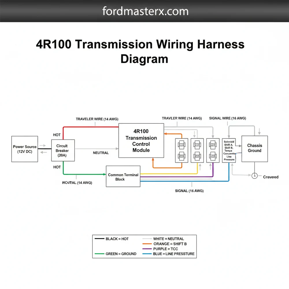
What does the 4R100 transmission wiring harness diagram show?
This diagram illustrates the electrical circuit paths, including the hot wire for power delivery and the ground wire for the control module. It details how the PCM interacts with the common terminal in the solenoid pack to manage gear changes, torque converter lockup, and line pressure regulation.
How many wires does the 4R100 solenoid connector have?
The primary connector for the 4R100 transmission features a 12-pin configuration. These pins include dedicated lines for the shift solenoids, the EPC solenoid, and the TCC solenoid. Each wire acts as a traveler wire for signals, ensuring the transmission responds correctly to the vehicle’s driving conditions.
What are the symptoms of a bad 4R100 transmission wiring harness?
Common symptoms include erratic shifting, the transmission being stuck in a single gear, or a flashing Overdrive light. These issues often stem from a frayed neutral wire or a shorted hot wire, which prevents the transmission control module from communicating effectively with the internal solenoid components.
Can I replace the 4R100 wiring harness myself?
Replacing the external harness is a straightforward DIY task that involves unplugging the old unit and routing the new one. However, replacing the internal harness requires dropping the transmission pan and fluid, which demands a higher level of mechanical skill and cleanliness to prevent hydraulic system contamination.
What tools do I need for testing the 4R100 harness?
You will need a digital multimeter to test for continuity and voltage at the common terminal. A basic socket set is required to remove heat shields or the transmission pan, while electrical contact cleaner is helpful for removing oxidation from the pins to ensure a solid connection.


