4 Wire Voltage Regulator Wiring Diagram: Easy Setup Guide
A 4 wire voltage regulator wiring diagram typically shows connections for the stator inputs (AC), the positive battery output (DC), and the ground. The regulator takes raw AC from the stator and converts it into a stable DC voltage to charge the battery while preventing overcharging through a dedicated ground wire connection.
📌 Key Takeaways
- Main purpose of this diagram is to convert AC stator output to stable DC battery voltage.
- The most important components to identify are the two AC input wires and the DC output.
- Safety requires a clean metal-to-metal ground connection to prevent regulator burnout.
- Always use a multimeter to verify that charging voltage stays between 13.5V and 14.5V.
- Use this diagram when repairing motorcycles, ATVs, or small engine charging systems.
Maintaining a stable electrical system in your vehicle or small engine equipment requires a precise understanding of how power is converted and distributed. If you are currently troubleshooting a charging issue or building a custom electrical harness, finding a clear 4 wire voltage regulator wiring diagram is the primary step toward a successful repair. This guide provides an in-depth look at how these four critical connections interact to transform raw alternating current from your stator into the steady direct current required to charge your battery and run your electronics. By following this technical breakdown, you will learn how to identify terminal pins, select the correct wire gauge, and ensure your system maintains the proper voltage without overheating or damaging sensitive components.
Decoding the 4 Wire Voltage Regulator Wiring Diagram
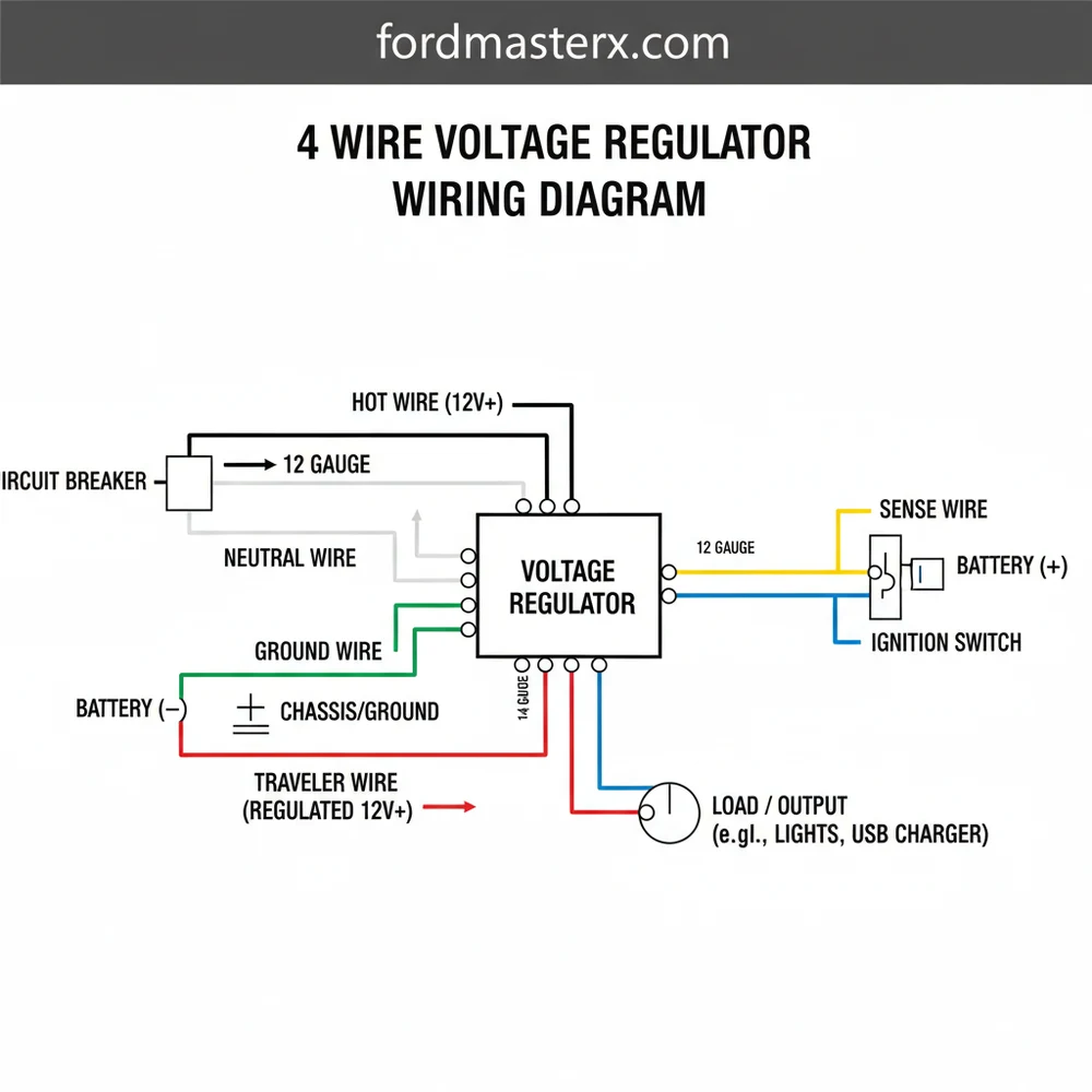
A 4 wire voltage regulator, often referred to as a rectifier-regulator, serves two main functions: it converts AC voltage into DC voltage and then limits that voltage to prevent battery overcharging. When looking at a 4 wire voltage regulator wiring diagram, you will typically see four distinct connection points. While color codes can vary by manufacturer, the standard configuration involves two input wires from the stator and two output wires leading to the battery and the chassis ground. Understanding the visual layout of these pins is essential before you begin making physical connections, as reversing the polarity can lead to an immediate failure of the internal diodes.
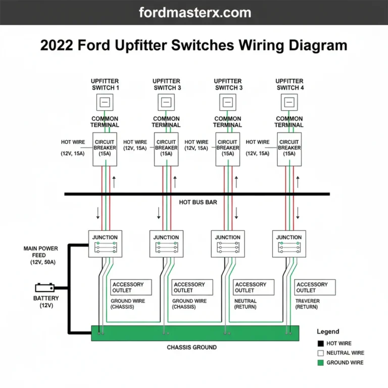
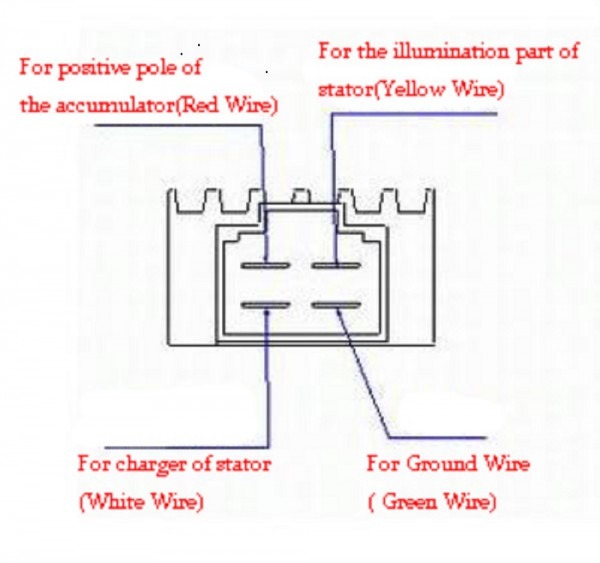
In most diagrams, the two “traveler wire” inputs are represented as receiving raw AC power directly from the alternator or stator. These are often yellow, white, or pink. Because AC current has no polarity, these two wires are typically interchangeable at the regulator input terminals. The remaining two wires represent the DC circuit. The “hot wire,” usually red, carries the regulated positive charge to the battery. The “common terminal” or ground wire, usually green or black, completes the circuit by connecting to the frame or the negative battery post. Identifying these by their position on the plug—often arranged in a square or a horizontal line—is the most reliable way to ensure your wiring matches the diagram’s specifications.
[4 WIRE VOLTAGE REGULATOR WIRING DIAGRAM VISUALIZATION]
Yellow
Input from Stator
Pink/Yellow
Input from Stator
Red
To Battery Positive
Green/Black
Common Ground
Standard Terminal Layout: Always verify with your specific component manual.
The diagram also accounts for the physical housing of the regulator. Most units feature a metal heat sink with cooling fins. It is important to note that some designs use the regulator’s casing itself as a secondary ground. In these instances, the brass screw used for mounting must make contact with clean, unpainted metal on the frame to ensure a low-resistance path for the common terminal circuit. If the diagram indicates a dedicated ground wire, do not rely solely on the mounting bolt; always run the specific ground wire to a verified grounding point to maintain consistent voltage levels across the entire RPM range of the engine.
Most 4-wire regulators are designed for permanent magnet stators. If your system has a field-excited alternator, a 4-wire regulator may not be compatible without a secondary excitation circuit. Always check the resistance of your stator coils before installing a new regulator.
Step-by-Step Installation and Wiring Guide
Reading a 4 wire voltage regulator wiring diagram is one thing; implementing it safely into a vehicle’s electrical system is another. Follow these detailed steps to ensure a professional-grade installation that protects your battery and electronics.
Step 1: Preparation and Safety
Before you begin any electrical work, disconnect the negative terminal from your battery. This prevents accidental shorts that could blow fuses or damage the stator. Gather your tools, including a high-quality crimping tool, heat shrink tubing, and a digital multimeter. Ensure you have the correct wire gauge for the job; for most small engine and powersports applications, 14 or 16-gauge automotive-grade copper wire is sufficient to handle the current load without excessive voltage drop.
Step 2: Identifying the Stator Travelers
Locate the two wires coming out of your engine’s stator housing. These are your “traveler wires.” In a standard 4-wire system, these wires carry AC voltage. Use your multimeter set to AC Volts to test them while the engine is running (if possible) or check for continuity between the two wires if the engine is off. These wires will connect to the two AC input pins identified on your 4 wire voltage regulator wiring diagram. Since it is AC power, the order does not matter; either stator wire can go to either AC pin on the regulator.
Step 3: Establishing the Common Terminal Ground
One of the most frequent causes of regulator failure is a poor ground. Locate the ground pin on the regulator (often Pin 4). Connect a dedicated ground wire from this terminal to a clean spot on the vehicle frame or directly to the negative terminal of the battery. If your regulator uses a brass screw for mounting as part of the grounding path, ensure the mounting surface is sanded free of paint and rust. A solid common terminal connection ensures the regulator can “dump” excess voltage efficiently, preventing the unit from burning out.
Never run the engine with the regulator disconnected from the battery. Without a battery to act as a “buffer,” the regulator will attempt to dissipate all generated energy as heat, which can lead to immediate internal thermal failure.
Step 4: Connecting the Hot Wire (DC Output)
The “hot wire” is the regulated DC output that charges the battery. Connect this wire from the regulator’s positive output pin (usually Pin 3, colored red) to the positive terminal of the battery. It is highly recommended to install an inline fuse (typically 15A to 20A) between the regulator and the battery. This protects the regulator and the stator in case of a short circuit further down the line in the vehicle’s main wiring harness.
Step 5: Securing the Neutral and Accessory Lines
In some specific 4-wire configurations, the fourth wire may act as a voltage sense wire or a “neutral” reference for the lighting circuit. Refer back to your specific 4 wire voltage regulator wiring diagram. If the diagram shows this wire going to a keyed ignition switch, ensure it is connected to a “switched” source. This tells the regulator when the vehicle is “on,” preventing it from draining the battery while the engine is off. However, in most standard rectifiers, the fourth wire is simply the ground.
Step 6: Final Mounting and Heat Dissipation
Regulators generate significant heat during the rectification process. Mount the unit in a location where it can receive adequate airflow. Do not hide it behind thick plastic bodywork or near exhaust pipes. Use the designated mounting holes and ensure any brass screw terminals are tightened to the manufacturer’s torque specifications to prevent vibration-induced loosening.
Step 7: Voltage Verification
Once all connections are secured, reconnect the battery. Start the engine and use your multimeter to measure the voltage across the battery terminals. At idle, you should see approximately 12.5V to 13.5V. As you increase the engine RPM, the voltage should climb but stay strictly between 14.0V and 14.8V. If the voltage exceeds 15V, the regulator is likely defective or improperly grounded.
Common Issues & Troubleshooting

Even with a perfect 4 wire voltage regulator wiring diagram, electrical gremlins can arise. The most common issue is “thermal runaway,” where the regulator becomes too hot to function, causing the output voltage to spike or drop. If you notice your headlights getting unusually bright as you rev the engine, or if your battery is bulging and hot to the touch, the regulator is failing to limit the voltage. This usually points to a failure in the internal zener diodes or a disconnected ground wire.
Another frequent problem is a “parasitic drain.” This happens when the hot wire or the sense wire (if applicable) allows current to flow back through the regulator into the stator coils while the engine is off. You can diagnose this by putting your multimeter in “Amps” mode and placing it in series with the battery’s positive cable. If you see a draw higher than a few milliamps with the key off, the regulator may have an internal short. Additionally, check for corroded traveler wire connectors. Corroded terminals increase resistance, which creates heat and can melt the plastic connector housing long before the regulator actually fails.
Use dielectric grease on all four pins of the regulator connector. This prevents moisture ingress and corrosion, which are the leading causes of high-resistance connections in powersports electrical systems.
Tips & Best Practices for Longevity
To ensure your charging system remains reliable for years to come, follow these best practices for maintenance and component selection. First, always prioritize the quality of your connections. While “vampire” or “T-tap” connectors are convenient, they are prone to failure in high-vibration environments. Instead, use soldered connections or high-quality crimp-and-seal terminals. Protecting your wiring with split-loom tubing or braided sleeving will also prevent the insulation from rubbing against the frame and creating a short circuit.
- ✓ Wire Gauge Selection: Always use at least 16 AWG wire for traveler wires and 14 AWG for the hot and ground wires to handle peak current.
- ✓ Heat Management: If mounting on a plastic surface, use a small aluminum backing plate to help dissipate heat away from the regulator body.
- ✓ Component Quality: Avoid extremely low-cost unbranded regulators. They often lack the sophisticated over-voltage protection circuits found in OEM or reputable aftermarket units.
- ✓ Terminal Maintenance: Periodically check the brass screw or mounting bolts for tightness, as thermal expansion and contraction can loosen them over time.
In conclusion, mastering the 4 wire voltage regulator wiring diagram is essential for anyone maintaining a modern charging system. By understanding the specific roles of the traveler wires, the hot wire, and the common terminal, you can effectively diagnose and repair charging issues with confidence. Remember that the regulator is the heart of your vehicle’s electrical health; keeping it well-grounded, adequately cooled, and correctly wired will ensure that your battery stays charged and your electrical components remain protected from damaging voltage spikes. Whether you are working on a vintage motorcycle, a modern ATV, or a garden tractor, the principles of the 4-wire system remain a constant and reliable foundation for electrical stability.
Frequently Asked Questions
Where is the 4 wire voltage regulator located?
In most small engines or motorcycles, the regulator is mounted on the engine block or the vehicle frame near the battery. It is often a finned aluminum box designed to dissipate heat generated during the voltage regulation process, ensuring it stays cool during operation.
What does a 4 wire voltage regulator wiring diagram show?
The diagram illustrates the electrical path from the stator’s alternating current to the regulator, then the regulated direct current to the battery. It identifies the two AC input wires, the single positive DC output wire, and the critical ground wire connection for the circuit.
How many wires does a 4 wire voltage regulator have?
As the name suggests, it features four distinct wires: two AC inputs from the stator, one DC positive output to charge the battery, and one ground wire. Some variations may use a common terminal for grounding, while others require a dedicated wire to the frame.
What are the symptoms of a bad 4 wire voltage regulator?
Common signs include a dead battery, dimming lights, or a battery that is leaking due to overcharging. If the regulator fails to limit voltage, you may see readings above 15 volts DC at the battery terminals, indicating the hot wire is delivering unregulated power.
Can I install this myself?
Yes, installing a 4 wire regulator is a straightforward DIY task for anyone familiar with basic electrical connections. By following a wiring diagram and identifying the hot wire and ground wire, you can safely replace the unit and restore your charging system in about 30 minutes.
What tools do I need for this task?
You will need a basic socket set or screwdrivers to mount the unit, a wire stripper for terminal connections, and a digital multimeter. The multimeter is essential for verifying that the hot wire is delivering the correct regulated voltage to the battery terminals.