4 Wire Fuel Pump Wiring Diagram: Easy Setup Guide
A 4 wire fuel pump wiring diagram illustrates two distinct circuits: the motor and the level sensor. The motor uses a thick hot wire for 12V power and a dedicated ground wire. The sensor utilizes two thinner wires, often involving a common terminal or traveler wire, to send fuel level data to the dashboard.
📌 Key Takeaways
- Differentiates between the high-current motor circuit and low-current sensor circuit
- Identifies the specific pinout for power, ground, and signal wires
- Ensures the fuel gauge functions correctly alongside the fuel pump
- Helps prevent electrical shorts by verifying the ground wire path
- Essential for fuel pump replacements or custom fuel cell installations
Successfully navigating a 4 wire fuel pump wiring diagram is a critical skill for any automotive DIYer or technician tasked with maintaining a vehicle’s fuel delivery system. Because the fuel pump is the primary component responsible for transporting gasoline from the tank to the engine, even a minor wiring error can lead to a complete vehicle breakdown or hazardous electrical shorts. By understanding how to interpret this specific diagram, you gain the ability to identify power sources, ground paths, and fuel level sensor signals with precision. This guide will walk you through the complexities of wire identification, terminal placement, and safety protocols, ensuring you have the knowledge to perform a professional-grade installation or repair.
Most modern 4-wire fuel pumps split their functionality between two circuits: two wires provide high-amperage power to the motor, while the other two handle the low-voltage signals for the fuel level sending unit.
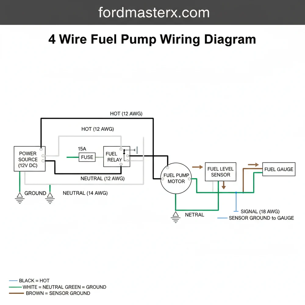
Decoding the 4 Wire Fuel Pump Wiring Diagram
When you first look at a 4 wire fuel pump wiring diagram, the layout can appear intimidating, but it is organized by function. In a standard four-pin configuration, the wires are divided into two distinct pairs. The first pair consists of the hot wire and the primary ground wire. These wires are typically a larger gauge than the others because they must carry significant current to turn the pump motor at high speeds. The hot wire delivers 12-volt battery power (usually via a fuel pump relay), while the ground wire completes the circuit to the vehicle’s chassis or battery negative terminal.
The second pair of wires is dedicated to the fuel level sending unit, which communicates the amount of fuel in your tank to the dashboard gauge. This pair includes a traveler wire (or signal wire) and a common terminal or sensor ground. The traveler wire carries a variable voltage or resistance signal based on the position of the float arm inside the tank. It is important to note that while household electrical systems use a neutral wire, in an automotive DC system, the “neutral” function is served by the sensor’s low-reference ground.
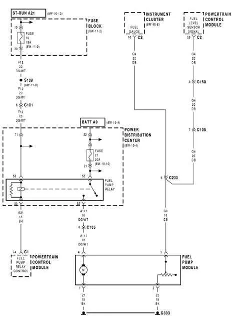
Visually, the diagram will show the connector pinout, often labeled A, B, C, and D, or 1, 2, 3, and 4. While color codes vary by manufacturer, a common convention uses a thick red or grey wire for the hot lead and a thick black wire for the ground. The sensor wires are often thinner, using colors like purple, white, or blue. Always refer to your specific vehicle’s service manual to confirm these colors, as a mistake here could send 12 volts directly into your delicate instrument cluster, causing permanent damage.
Step-by-Step Installation and Wiring Guide

Following a 4 wire fuel pump wiring diagram requires a methodical approach to ensure every connection is secure and electrically sound. Before beginning, ensure you have the necessary tools: a digital multimeter, wire strippers, high-quality crimping tools, and heat-shrink tubing.
- ✓ Multimeter for testing voltage and continuity
- ✓ Marine-grade heat shrink butt connectors
- ✓ Electrical contact cleaner
- ✓ Wire loom for abrasion protection
Step 1: Identify the Pin Assignments
Consult your diagram to determine which pin corresponds to which function. Typically, the two larger terminals on the pump housing are for the motor (Power and Ground), while the two smaller terminals are for the fuel sender. If you are using a universal pump, look for markings near the base; you might see a (+) for the hot wire and a (-) for the ground wire.
Step 2: Prepare the Wiring Harness
Strip approximately 1/4 inch of insulation from the ends of your vehicle’s harness and the new pump pigtail. Ensure the wire gauge matches the factory specifications; using wire that is too thin for the motor power can cause overheating and premature pump failure. If your pump uses a brass screw terminal style rather than a plastic plug, ensure you use ring terminals for a secure fit.
Step 3: Connect the High-Current Motor Wires
Connect the hot wire from the relay to the positive terminal of the pump. Following this, connect the primary ground wire to a clean, unpainted metal surface on the chassis or back to the designated ground distribution block. Secure these connections using heat-shrink connectors to prevent moisture from causing corrosion inside the fuel tank area.
Step 4: Wire the Fuel Level Sensor
Connect the traveler wire from the fuel gauge to the signal pin on the pump assembly. Then, connect the common terminal or sensor ground wire. It is vital not to swap the motor ground with the sensor ground, as the sensor ground is often “cleaner” and processed differently by the vehicle’s computer (ECU).
Step 5: Verify Voltage and Continuity
Before final installation into the tank, turn the ignition to the “ON” position (do not start the engine). Use your multimeter to check for 12V voltage at the hot wire. It should prime for 2-3 seconds and then drop off. Check the resistance on the traveler wire by moving the float arm; the Ohms should change smoothly as the arm moves.
Always disconnect the negative battery terminal before performing any wiring work near the fuel tank. Gasoline vapors are highly flammable, and a single spark from a shorted wire can lead to a fire or explosion.
Common Issues & Troubleshooting
Even with a perfect 4 wire fuel pump wiring diagram, issues can arise during or after installation. One of the most frequent problems is a “no-start” condition caused by a poor ground. If the ground wire is attached to a rusted or painted surface, the pump will not receive enough current to build pressure, even if your multimeter shows 12V at the hot lead.
Another common issue involves the fuel gauge reading “Empty” or “Full” constantly regardless of the actual fuel level. This usually points to a problem with the traveler wire or the common terminal. If the traveler wire is shorted to ground, the gauge will usually peg to one extreme. If there is an open circuit (a broken wire), it will peg to the other.
If your fuel pump runs but your gauge doesn’t work, try swapping the two sensor wires. Unlike the motor wires, the sensor wires in some older 4-wire systems are resistive and may work more accurately when oriented correctly to the gauge’s internal pull-up resistor.
If you encounter intermittent pump operation, check the connector pins for “tension.” Over time, the female terminals in the plug can spread apart, leading to a loose connection that heats up and eventually melts the plastic housing. Use a small pick tool to gently tighten the terminals for a snug fit on the pump pins.
Tips & Best Practices for Long-Term Reliability
To ensure your fuel system remains reliable for years to come, follow these best practices. First, always use fuel-resistant wiring if any part of the harness will be submerged inside the tank. Standard automotive wire insulation can degrade when exposed to modern ethanol-blended fuels, leading to a “neutral wire” style short circuit where the signal bleeds into the ground.
When making external connections, avoid using “T-taps” or “Scotch locks.” These connectors cut into the wire strands and create a point of failure for moisture and vibration. Instead, use a proper crimp and solder technique, or high-quality heat-shrink butt connectors. If your pump assembly uses a brass screw for grounding, apply a small amount of dielectric grease to the terminal to prevent oxidation, which is the number one killer of fuel pump circuits.
Finally, consider the age of your vehicle’s relay. A fuel pump relay’s internal contacts can wear out, leading to a voltage drop. If the pump is receiving 10.5V instead of 12.6V, it will run slower, run hotter, and fail prematurely. Replacing the relay whenever you replace the pump is a cost-effective insurance policy for your new component.
By strictly adhering to the 4 wire fuel pump wiring diagram and focusing on high-quality connections, you ensure that your vehicle’s engine receives a steady, reliable flow of fuel. Whether you are identifying the hot wire for power or the traveler wire for your gauge, precision and patience are your best tools for a successful project. Always double-check your pinouts and test your circuits before sealing the tank to avoid having to do the job twice.
Frequently Asked Questions
Where is the fuel pump connector located?
The connector is typically located on the top of the fuel tank assembly. On many vehicles, you can access it through a removable service panel under the rear seat. If no panel is present, the fuel tank must be lowered to access the wiring harness and common terminal connection.
What does a 4 wire fuel pump wiring diagram show?
This diagram illustrates the electrical path for both the fuel pump motor and the level sending unit. It specifies which hot wire carries 12V power, which leads are for the ground wire, and how the traveler wire transmits resistance signals to the fuel gauge for accurate readings.
How many connections does a 4 wire fuel pump have?
A 4 wire fuel pump has four electrical connections. Two thicker wires serve as the hot wire and ground wire for the DC motor. The other two thinner wires function as the fuel level sensor leads, providing the signal and return path (neutral wire) for the fuel gauge system.
What are the symptoms of a bad fuel pump?
Symptoms include an engine that cranks but won’t start, sudden stalling, or a high-pitched whining sound from the tank. If the fuel gauge is stuck or erratic, it usually points to a fault in the sensor wires or a loose traveler wire rather than the pump motor itself.
Can I install or replace this myself?
Yes, replacing a fuel pump is a common DIY task if you follow a 4 wire fuel pump wiring diagram. You must depressurize the fuel system and disconnect the battery first. The job may require a fuel tank jack if the vehicle lacks an interior access port.
What tools do I need for fuel pump wiring?
You will need a digital multimeter to verify 12V on the hot wire and check for a solid ground wire connection. Basic tools like a socket set, fuel line disconnect tools, and wire crimpers are necessary. Use heat-shrink tubing to protect any repaired wires from fuel vapors.