4 Wire Alternator Wiring Diagram: Easy Setup Guide
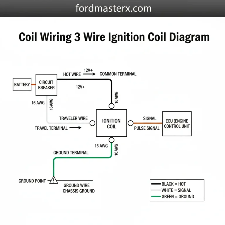
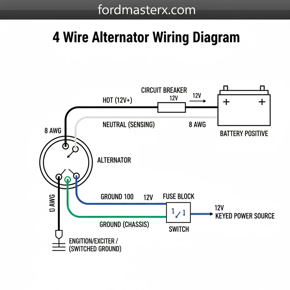
A 4 wire alternator wiring diagram shows the connections for the battery output, voltage sensing, ignition input, and warning light. The hot wire carries charging current to the battery, while the sense wire connects to a common terminal to monitor voltage. Proper grounding through a dedicated ground wire ensures the circuit remains stable.
📌 Key Takeaways
- The diagram clarifies the distinction between power, sensing, and signal leads
- Identify the ‘S’ or sensing terminal as the most critical for voltage regulation
- Always disconnect the battery before attempting any wiring to prevent shorts
- Use a multimeter to verify that the hot wire shows battery voltage when off
- This diagram is essential when upgrading from older 1-wire or 3-wire systems
Understanding the complexities of your vehicle’s charging system is essential for any DIY mechanic or restoration enthusiast. If you are currently facing a pile of disconnected leads or a flickering battery light, finding a precise 4 wire alternator wiring diagram is the first step toward a reliable repair. This specific configuration, common in many high-output systems like the GM CS130 series, provides superior voltage regulation compared to simpler setups. By mastering this diagram, you will learn how to properly excite the alternator, sense system voltage at a remote point, and ensure your battery remains fully charged even under heavy electrical loads.
Decoding the 4 Wire Alternator Wiring Diagram
A 4 wire alternator wiring diagram typically illustrates the connections for a multi-terminal plug alongside the primary battery output. While the name implies four wires, there is actually a fifth heavy-duty connection for the main power output. The primary goal of this diagram is to show how the internal voltage regulator communicates with the rest of the vehicle. Unlike a residential electrical circuit where you might find a traveler wire or a common terminal on a switch, an automotive alternator uses specific pins often labeled S, F, L, and P.
In a standard diagram, you will see a large-gauge hot wire connecting the “B+” or “BAT” terminal directly to the positive battery post or a starter solenoid. The four smaller wires in the connector plug serve distinct purposes. The “S” terminal is the Sense wire, which monitors battery voltage. The “L” terminal is the Lamp or Indicator wire, which triggers the dashboard warning light and “excites” the alternator to start charging. The “F” or “I” terminal is for the Field or Ignition connection, and the “P” or “R” terminal provides a Stator signal, often used for tachometers in diesel applications.
In most 4-wire applications, you do not necessarily have to use all four pins. Many custom builds only utilize the ‘S’ and ‘L’ pins to achieve full charging functionality, while the others remain for specific accessory signals.
The visual layout of the plug is vital. Most diagrams will show the plug from the perspective of the wire-entry side or the terminal face. The wires are usually color-coded: red for sensing, brown for the lamp, and black for the ground wire. Proper identification prevents the catastrophic failure of the internal regulator. If you are comparing this to home wiring, think of the main B+ wire as the hot wire, though automotive systems function on a DC loop where the chassis serves as the return path rather than a dedicated neutral wire found in AC systems.
Step-by-Step Installation and Wiring Guide

Following a 4 wire alternator wiring diagram requires a methodical approach to ensure every terminal receives the correct signal at the right time. Follow these steps to complete your installation securely.
- ✓ Step 1: Disconnect the Battery. Always begin by removing the negative battery cable. This prevents accidental shorts that can fry the new alternator’s regulator or damage your vehicle’s sensitive electronics.
- ✓ Step 2: Connect the Main Battery Output (B+). Use a large 4 to 8 gauge wire for this connection. Secure the ring terminal to the threaded post on the back of the alternator. This is the main “hot wire” that delivers the charging current to the battery. Ensure the nut is tight but do not over-torque it.
- ✓ Step 3: Wire the Sense (S) Terminal. This wire should be routed to a point where you want the alternator to “read” the voltage. For the most accurate charging, connect this to the main power distribution block or the positive battery terminal. This helps the alternator compensate for any voltage drop in the main wiring.
- ✓ Step 4: Wire the Lamp/Exciter (L) Terminal. This is the most critical small wire. It must connect to a switched ignition source through a light bulb (the dash warning light) or a resistor. This wire provides the initial voltage needed to start the charging process. Without this, the alternator may not charge until the engine hits very high RPMs.
- ✓ Step 5: Address the F and P Terminals. In most standard 12V automotive setups, the F (Field) and P (Phase) terminals are left unused. If your vehicle has an external computer controlling the field or a mechanical tachometer, consult your specific vehicle manual to bridge these connections.
- ✓ Step 6: Verify the Grounding. While most alternators ground through their mounting brackets, it is best practice to run a dedicated ground wire from the alternator housing to the engine block or the negative battery terminal.
- ✓ Step 7: Final Inspection and Testing. Reconnect the battery. Use a multimeter to check the voltage at the battery while the engine is running. It should read between 13.8V and 14.4V.
Never connect the ‘L’ terminal directly to a 12V ignition source without a lamp or resistor. Doing so will apply too much current to the regulator, causing it to burn out instantly upon starting the engine.
To complete this job, you will need a few basic tools: a high-quality crimping tool, a wire stripper, a multimeter, and a set of sockets or wrenches. While you won’t encounter a brass screw like those on a light switch, you will need high-quality ring terminals and a proper weather-pack connector for the 4-pin plug to ensure a moisture-resistant connection.
Common Issues & Troubleshooting

Even with a 4 wire alternator wiring diagram in hand, errors can occur. The most common problem is a “no charge” condition, which usually stems from a fault in the ‘L’ (Lamp) circuit. If the dashboard bulb is burnt out, the circuit is broken, and the alternator won’t excite. Using a multimeter, check for 12V at the ‘L’ pin when the ignition is on but the engine is off.
Another frequent issue is a parasitic battery drain. This often happens if the ‘S’ (Sense) wire or ‘L’ wire is connected to a constant power source rather than a switched one. This keeps the internal regulator “awake,” slowly pulling current even when the car is parked. If you notice your battery dies overnight, use the diagram to verify that your exciter wire is only “hot” when the key is in the ‘on’ or ‘run’ position.
Overcharging is less common but equally dangerous, often caused by a break in the ‘S’ wire. If the regulator cannot “see” the battery voltage, it may default to full output, potentially boiling the battery and damaging other electrical components. Watch for a voltage reading above 15V as a warning sign of this failure.
Tips & Best Practices for Alternator Maintenance
To ensure your charging system remains reliable, choosing the correct wire gauge is paramount. For the main B+ hot wire, always use a gauge rated for at least 125% of the alternator’s maximum amperage output. For a 100-amp alternator, an 8-gauge wire is the minimum, while a 150-amp unit should use 4-gauge or larger.
Always use “marine grade” tinned copper wire if your vehicle is operated in high-moisture or salt-air environments. This prevents internal corrosion that can lead to high resistance and heat buildup over time.
When installing your 4 wire alternator, pay close attention to the cleanliness of the mounting surfaces. Since the alternator relies on its casing for ground, any rust or paint on the bracket can impede current flow. If you are unsure about the ground path, adding a dedicated 10-gauge ground wire from the alternator’s case directly to the frame is an inexpensive way to ensure stable voltage.
Finally, always use heat-shrink tubing on your connections. Unlike the simple screw terminals found in home wiring, automotive environments are subject to vibration and extreme temperature swings. Quality components like copper ring terminals and nylon-insulated connectors will save you money in the long run by preventing roadside failures. By following your 4 wire alternator wiring diagram and adhering to these best practices, you can enjoy a high-performance charging system that will last for years.
Frequently Asked Questions
Where is the 4 wire alternator located?
The 4 wire alternator is typically located at the front of the engine, mounted to a bracket and driven by the serpentine or V-belt. It is positioned near the battery to minimize the length of the heavy-gauge hot wire required to deliver charging current to the electrical system.
What does a 4 wire alternator wiring diagram show?
This diagram illustrates the four primary connections: the main battery output, the remote voltage sense wire, the ignition trigger, and the dashboard indicator lamp circuit. It shows how the traveler wire moves signals from the ignition switch to the common terminal on the alternator to initiate the charging process.
How many wires does this alternator have?
A 4 wire alternator features four distinct electrical connections. These include the main B+ output for charging, a sense wire for voltage regulation, an ignition lead to turn the regulator on, and a lamp wire for the dashboard. A separate ground wire or the alternator case provides the return path.
What are the symptoms of a bad 4 wire alternator?
Symptoms include a discharging battery, dimming headlights, or a dashboard warning light that stays illuminated. If the internal neutral wire or stator fails, you may hear a whining noise. Inaccurate voltage sensing can also lead to overcharging, which smells like sulfur or causes the battery to leak acid.
Can I install this myself?
Yes, installing a 4 wire alternator is a manageable DIY task for most vehicle owners. By following the wiring diagram, you can ensure each lead is connected to its respective common terminal. As long as you follow safety protocols and use the correct wire gauges, the installation is very straightforward.
What tools do I need for installation?
To install a 4 wire alternator, you will need a basic socket set to remove mounting bolts and a belt tensioner tool. A digital multimeter is essential for testing the hot wire voltage. You may also need wire strippers and crimpers if you are repairing or replacing any connectors.