4 Solenoid Winch Wiring Diagram: Easy Setup Guide
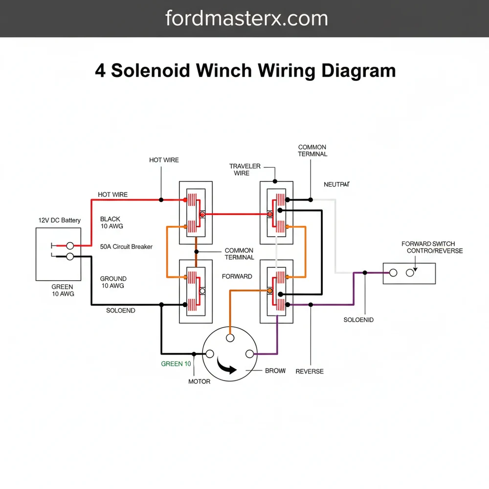
A 4 solenoid winch wiring diagram illustrates the bridge circuit connecting the battery, switch, and motor. It uses four solenoids to reverse polarity, allowing the motor to spool in and out. Connect the hot wire to the common terminal, ensuring the ground wire is secure for safe operation and circuit completion.
📌 Key Takeaways
- Visualizes the polarity reversal needed for winch operation
- Helps identify the common terminal for power distribution
- Ensures connections are tightened to prevent heat buildup
- Utilizes color-coded traveler wires for easy circuit identification
- Essential for rebuilding or repairing older winch control boxes
If you are working with a classic recovery winch or a heavy-duty industrial setup, understanding the 4 solenoid winch wiring diagram is the key to a successful installation. This configuration, often referred to as a solenoid pack or control box, is the electrical “brain” that tells your winch motor when to spool in, spool out, or stop. Unlike modern sealed contactors, a four-solenoid system uses individual electromagnetic switches to manage high-current loads. In this guide, you will learn how to identify each terminal, understand the flow of electricity through the control circuit, and master the connections required to get your winch running reliably. We will cover wire color conventions, the importance of proper gauge selection, and the specific sequence needed to prevent electrical shorts.
Understanding the 4 Solenoid Winch Wiring Diagram Layout
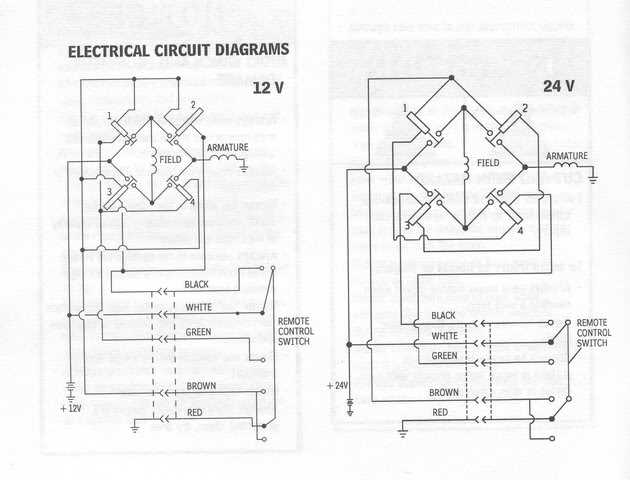
The 4 solenoid winch wiring diagram represents an H-bridge circuit designed to reverse the polarity of a DC motor. In a typical setup, four independent solenoids are mounted on a bracket. Each solenoid acts as a high-current relay. When you press the button on your remote, you are sending a low-current signal to a specific pair of these solenoids. This causes them to close their internal contacts, allowing high-amperage current to flow from the battery to the winch motor.
The diagram visually separates the system into two distinct paths: the power circuit and the control circuit. The power circuit involves thick heavy-duty cables, often 2-gauge or 4-gauge, which carry the massive current required to pull a vehicle. These cables connect the hot wire from the battery to the main “common terminal” bus bars on the solenoids. The control circuit, on the other hand, utilizes thinner wires connected to a small brass screw on each solenoid. This is where the traveler wire from your remote control switch attaches.
In a standard 12V or 24V system, the solenoids are paired. Two solenoids handle the “In” function, and two handle the “Out” function. The wiring diagram shows how the bridge plates connect the solenoids together, ensuring that when one pair is active, the electricity flows in one direction through the motor’s field coils, and when the other pair is active, the flow is reversed. Understanding this layout is crucial because misidentifying a single traveler wire or ground wire can result in a dead short or a winch that runs uncontrollably as soon as the battery is connected.
[DIAGRAM_PLACEHOLDER: A visual representation showing four solenoids arranged in a square. The top two solenoids are connected by a copper bus bar labeled ‘Positive Feed’. The bottom two are connected to the ‘Motor Ground’. Signal wires (Traveler wires) from the remote plug connect to the small brass terminals on each solenoid. Large gauge cables connect to motor terminals A, F1, and F2.]
Step-by-Step Installation Guide for a 4 Solenoid System
Wiring a winch requires precision and a strict adherence to safety protocols. Follow these steps to interpret the 4 solenoid winch wiring diagram and complete your installation safely.
Always disconnect your vehicle’s battery before starting the wiring process. A short circuit in a high-amperage winch cable can cause immediate fires or battery explosions. Ensure all tools are insulated.
- Identify the Motor Terminals: Most winch motors have three main terminals labeled A (Armature), F1 (Field 1), and F2 (Field 2). Look at your motor casing to locate these. The A terminal is usually the one that receives the ground wire or a specific power feed depending on the motor type (Series Wound vs. Permanent Magnet).
- Mount the Solenoid Pack: Secure the four solenoids to their mounting bracket inside the control box. Ensure the bracket is clean to allow for a solid ground connection if the solenoids are self-grounding through their base. If they are not self-grounding, you will need to run a small ground wire to the base of each solenoid.
- Install the Main Hot Wire: Take your heaviest gauge red cable and connect it from the positive terminal of the battery to the main power bus bar on the solenoid pack. This bus bar typically links the two “input” studs on the top solenoids. Ensure the connection is tight and covered with a rubber boot.
- Connect the Bridge Plates: Using the copper bus bars or heavy-duty jumper wires, connect the solenoids according to the diagram. This usually involves linking the output of solenoid 1 to solenoid 3, and solenoid 2 to solenoid 4. This creates the “reversing” capability of the system.
- Wire the Remote Control Socket: The remote socket usually has three or four wires. The “common terminal” wire on the socket needs a 12V positive feed (often tapped from the main hot wire). The other two wires are the traveler wire “In” and traveler wire “Out.” Connect the “In” traveler wire to the brass screw terminals of the first pair of solenoids. Connect the “Out” traveler wire to the second pair.
- Attach Motor Lead Cables: Run three heavy gauge cables from the solenoid pack to the motor. Following your 4 solenoid winch wiring diagram, connect the corresponding solenoid outputs to terminals F1, F2, and A on the motor. In most series-wound motors, F1 and F2 determine direction, while A completes the circuit.
- Grounding the System: Connect a heavy gauge black ground wire from the negative terminal of the battery directly to the ground bolt on the winch motor (often located on the bottom or side). Do not rely on the vehicle’s chassis for grounding, as the high voltage and current demands of a winch require a direct path back to the battery.
While AC systems use a neutral wire, DC winch systems use a dedicated ground wire. In the context of winch remotes, some users refer to the ground or return wire as the neutral wire, but technically it is the negative return path to the battery.
Common Issues and Troubleshooting

Even with a perfect 4 solenoid winch wiring diagram, issues can arise due to environmental factors or component wear. Troubleshooting a 4-solenoid system is often easier than a modern contactor because you can test each component individually.
- ✓ Rapid Clicking Sound: This usually indicates that the solenoids are receiving enough voltage to trigger the internal magnet but the battery doesn’t have enough current to hold them closed, or there is a poor ground wire connection.
- ✓ Winch Works in One Direction Only: This is a classic sign of a failed solenoid or a disconnected traveler wire. Check the brass screw connections on the solenoids responsible for the non-working direction.
- ✓ Excessive Heat at Terminals: Heat is caused by resistance. This usually means a terminal nut is loose or the wire gauge is too thin for the load. Ensure all nuts on the brass screw and large studs are torqued properly.
- ✓ The “Dead” Winch: If nothing happens, check the main hot wire fuse (if installed) and use a multimeter to ensure 12V is reaching the common terminal of the remote switch.
If you suspect a solenoid has failed, you can test it by applying a 12V jumper wire directly to the small brass screw (trigger terminal). If the solenoid clicks and shows continuity across the large studs, it is functioning. If it remains silent or doesn’t pass current, it needs replacement.
Tips and Best Practices for Long-Term Reliability
To ensure your winch remains ready for action when you’re stuck in the mud, follow these professional maintenance and installation tips.
Apply a small amount of dielectric grease to every connection point, including the brass screw signal terminals and the large battery lugs. This prevents corrosion and ensures consistent voltage delivery in wet environments.
Choose the Right Gauge: Never undersize your cables. For most winches in the 8,000lb to 12,000lb range, a 2-gauge copper wire is the minimum recommendation. Using a thinner wire will cause a significant voltage drop, reducing the winch’s pulling power and potentially melting the insulation.
Component Quality: When replacing solenoids, look for units with silver alloy contact points and high-quality brass screw terminals. Cheap solenoids often use thin copper plating that can weld itself shut under high heat, causing the winch to run uncontrollably.
Regular Maintenance: Once a season, open the control box and inspect the wiring. Look for frayed insulation or signs of “blue” corrosion on the terminals. Tighten the common terminal nuts, as vehicle vibrations can loosen them over time.
Remote Control Safety: If you are using a wireless remote, ensure the receiver is wired into the 4 solenoid winch wiring diagram with a master kill switch. This prevents accidental activation which can damage the winch or vehicle if the hook is still attached to the bumper.
By following this 4 solenoid winch wiring diagram guide, you have the technical foundation to build a robust and reliable recovery system. Whether you are replacing old components or starting a fresh install, proper terminal identification, correct wire gauge selection, and secure connections will ensure your winch performs at its peak when the terrain gets tough. Proper wiring is not just about functionality; it is about the safety of you and your vehicle during high-stress recovery operations.
Frequently Asked Questions
Where is the solenoid box located?
The solenoid box is typically located on top of the winch motor or mounted nearby on the vehicle frame. It houses the four solenoids that control current flow. Keeping it in a dry, accessible location protects the traveler wire connections and makes future maintenance or troubleshooting much simpler.
What does this wiring diagram show?
This 4 solenoid winch wiring diagram shows the electrical path from the battery to the motor. It details how the neutral wire and hot wire interface with the solenoids to reverse motor direction. It is essential for understanding how the remote switch triggers specific solenoids to spool the cable.
How many connections does a 4 solenoid winch have?
A standard setup has several connections: three main cables to the winch motor (F1, F2, and Armature), a main hot wire from the battery, and a ground wire. Each solenoid also has small control terminals for the switch wires, often involving a common terminal for shared power.
What are the symptoms of a bad solenoid?
Symptoms include a winch that only spools in one direction, clicking sounds without movement, or total failure to activate. This often indicates a burnt contact or a loose traveler wire. Testing the common terminal with a multimeter can help determine if power is reaching the solenoid unit effectively.
Can I install this myself?
Yes, you can install this yourself if you have basic electrical knowledge and the correct tools. Following a 4 solenoid winch wiring diagram is crucial for safety. Ensure all high-current cables are properly insulated and that the ground wire is connected to a clean, unpainted metal surface.
What tools do I need for this task?
You will need a set of wrenches or sockets to tighten terminal nuts, wire strippers for the control cables, and a multimeter for testing continuity. Heat shrink tubing and a crimping tool are also recommended to ensure the traveler wire and main power leads remain weather-resistant and secure.